
okay i did search but im not comin up with the fix so heres my scenario. i have a 92 harness and my pump wont prime. i checked all fusible links and they r good. i have no constant power to relay but i do have power on the green and yellow wire. all sensors are working and i have power to the green and red wire to the coil. when i put constant power to the pink and black wire on the fp relay it ran but all the time. i have two wires near the drivers side firewall that might be the problem. the big red and green wire comin frominside the cab is hot with the key on. these are the wires that plug into the main harness. the other goes to the starter solenoid safety switch. my brother had the same problems with this harness so im trying to fix it the factory way. please help. also if the coil has power to it should the coil wire for the plugs be hot all the time or only when u crank it
You are using an out of date browser. It may not display this or other websites correctly.
You should upgrade or use an alternative browser.
You should upgrade or use an alternative browser.
another fuel pump issue
- Thread starter pa308
- Start date
There are no clues in your sig as to what year the car is. The electrical wiring changed several times between 79 and 93.
You are aware that the 92 harness places the fuel pump relay under the hood near the A/C WOT relay and Mass Air Meter.
If this is a mass air conversion, the relay under the seat does not work anymore.
Going on the basis that this is a 93 model car, here is the test path for 91-93 Mustangs.
Fuel Pump Troubleshooting for 91-93 Mustangs
Clue – listen for the fuel pump to prime when you first turn the ignition switch on.
It should run for 5-20 seconds and shut off. To trick the fuel pump into running,
find the ECC test connector and jump the connector in the lower RH corner to
ground.

If the fuse links are OK, you will have power to the pump. Check fuel pressure –
remove the cap from the Schrader valve behind the alternator and depress the
core. Fuel should squirt out, catch it in a rag. A tire pressure gauge can also be
used if you have one - look for 37-40 PSI. Beware of fire hazard when you do this.
No fuel pressure, possible failed items in order of their probability:
A.) Tripped inertia switch – press reset button on the inertia switch. The hatch
cars hide it under the plastic trim covering the driver's side taillight. Use the
voltmeter or test light to make sure you have power to both sides of the switch
B.) Fuel pump Relay: On 92 and later model cars it is located below the Mass Air Flow meter.
C.) Clogged fuel filter
D.) Failed fuel pump
E.) Blown fuse link in wiring harness.
F.) Fuel pressure regulator failed. Remove vacuum line from regulator and inspect
for fuel escaping while pump is running.
The electrical circuit for the fuel pump has two paths, a control path and a power
path.
The control path consists of the computer, and the fuel pump relay coil. It turns
the fuel pump relay on or off under computer control. The switched power (red
wire) from the ECC relay goes to the relay coil and then from the relay coil to the
computer (light blue\orange wire). The computer provides the ground path to
complete the circuit. This ground causes the relay coil to energize and close the
contacts for the power path. Keep in mind that you can have voltage to all the
right places, but the computer must provide a ground. If there is no ground, the
relay will not close the power contacts.
The power path picks up from a fuse link near the starter relay. Fuse links are like
fuses, except they are pieces of wire and are made right into the wiring harness.
The feed wire from the fuse link (pink/black wire) goes to the fuel pump relay
contacts. When the contacts close because the relay energizes, the power flows
through the pink/black wire to the contacts and through the dark green\yellow
wire to the inertia switch. The other side of the inertia switch with the
brown\pink wire joins the pink/black wire that connects to the fuel pump. The fuel
pump has a black wire that supplies the ground to complete the circuit.
Remember that the computer does not source any power to actuators, relays
or injectors, but provides the ground necessary to complete the circuit. That
means one side of the circuit will always be hot, and the other side will go to
ground or below 1 volt as the computer switches on that circuit.
Diagram courtesy of Tmoss & Stang&2birds
diagram of the wiring for 91-93 cars.

Power circuits:
Power feed: Look for 12 volts at the pink/black wire (power source for fuel pump relay).
No voltage or low voltage, bad fuse link, bad wiring, or connections. Remember that on 92
or later models the fuel pump relay is located under the Mass Air meter. Watch out for the
WOT A/C control relay on these cars, as it is located in the same place and can easily be
mistaken for the fuel pump relay.
Relay: Turn on the key and jumper the ECC test connector as previously described. Look
for 12 volts at the dark green\yellow wire (relay controlled power for the fuel pump). No
voltage there means that the relay has failed, or there is a broken wire in the relay control circuit.
Inertia switch: Check the brown/pink wire, it should have 12 volts. No 12 volts there, either
the inertia switch is open or has no power to it. Check both sides of the inertia switch: there
should be power on the dark green\yellow (inertia switch input) and brown/pink wire
(inertia switch output). Power on the dark green\yellow wire and not on the brown/pink wire
means the inertia switch is open. Press on the red plunger to reset it to the closed position.
Sometimes the inertia switch will be intermittent or will not pass full power. Be sure that
there is 12 volts on both sides of the switch with the pump running and that the voltage drop
measured across the switch is less than .75 volts.
Control circuits:
Relay: The red wire for the fuel pump relay coil gets its power feed from the ECC relay.
No 12 volts here, and the ECC relay has failed or there is bad wiring or bad connections
coming from it. The ECC relay is located on top of the computer, which is under the passenger’s
side kick panel. It is not easy to get to, you must have small hands or pull the passenger side
dash speaker out to access it.
Relay: The light blue/orange wire provides a ground path for the relay power. With the test
connector jumpered according to the previous instructions, there should be less than .75 volts.
Use a test lamp with one side connected to battery power and the other side to the light blue/orange
wire on the fuel pump relay. The test light should glow brightly. No glow and you have a broken
wire or bad connection between the test connector and the relay. To test the wiring from the
computer, remove the passenger side kick panel and disconnect the computer connector.
It has a 10 MM bolt that holds it in place. Remove the test jumper from the ECC test connector.
With the test lamp connected to power, jumper pin 22 to ground and the test lamp should glow.
No glow and the wiring between the computer and the fuel pump relay is bad.
Computer: If you got this far and everything else checked out good, the computer is suspect .
Remove the test jumper from the ECC test connector located under the hood . Remove the
plastic cover over the computer wiring, but leave the computer wiring connector plugged
into the computer. With the ignition switch in the run position, connect a test lamp to the
battery and back probe pin 22, the light blue/orange wire with it. The lamp should glow
brightly. No glow and the computer has died a sad death. If you used a voltmeter instead
of a test lamp, you should see battery voltage, whatever that may be…
See the following website for some help from Tmoss (diagram designer) & Stang&2Birds (website host) for help
on 88-95 wiring http://www.veryuseful.com/mustang/tech/engine/
Fuel pump runs continuously: The light blue/orange wire has shorted to ground. Disconnect
the computer and use an ohmmeter to check out the resistance between the light blue/orange
wire and ground. You should see more than 10 K Ohms (10,000 ohms) or an infinite open
circuit. Be sure that the test connector isn’t jumpered to ground.
You are aware that the 92 harness places the fuel pump relay under the hood near the A/C WOT relay and Mass Air Meter.
If this is a mass air conversion, the relay under the seat does not work anymore.
Going on the basis that this is a 93 model car, here is the test path for 91-93 Mustangs.
Fuel Pump Troubleshooting for 91-93 Mustangs
Clue – listen for the fuel pump to prime when you first turn the ignition switch on.
It should run for 5-20 seconds and shut off. To trick the fuel pump into running,
find the ECC test connector and jump the connector in the lower RH corner to
ground.
If the fuse links are OK, you will have power to the pump. Check fuel pressure –
remove the cap from the Schrader valve behind the alternator and depress the
core. Fuel should squirt out, catch it in a rag. A tire pressure gauge can also be
used if you have one - look for 37-40 PSI. Beware of fire hazard when you do this.
No fuel pressure, possible failed items in order of their probability:
A.) Tripped inertia switch – press reset button on the inertia switch. The hatch
cars hide it under the plastic trim covering the driver's side taillight. Use the
voltmeter or test light to make sure you have power to both sides of the switch
B.) Fuel pump Relay: On 92 and later model cars it is located below the Mass Air Flow meter.
C.) Clogged fuel filter
D.) Failed fuel pump
E.) Blown fuse link in wiring harness.
F.) Fuel pressure regulator failed. Remove vacuum line from regulator and inspect
for fuel escaping while pump is running.
The electrical circuit for the fuel pump has two paths, a control path and a power
path.
The control path consists of the computer, and the fuel pump relay coil. It turns
the fuel pump relay on or off under computer control. The switched power (red
wire) from the ECC relay goes to the relay coil and then from the relay coil to the
computer (light blue\orange wire). The computer provides the ground path to
complete the circuit. This ground causes the relay coil to energize and close the
contacts for the power path. Keep in mind that you can have voltage to all the
right places, but the computer must provide a ground. If there is no ground, the
relay will not close the power contacts.
The power path picks up from a fuse link near the starter relay. Fuse links are like
fuses, except they are pieces of wire and are made right into the wiring harness.
The feed wire from the fuse link (pink/black wire) goes to the fuel pump relay
contacts. When the contacts close because the relay energizes, the power flows
through the pink/black wire to the contacts and through the dark green\yellow
wire to the inertia switch. The other side of the inertia switch with the
brown\pink wire joins the pink/black wire that connects to the fuel pump. The fuel
pump has a black wire that supplies the ground to complete the circuit.
Remember that the computer does not source any power to actuators, relays
or injectors, but provides the ground necessary to complete the circuit. That
means one side of the circuit will always be hot, and the other side will go to
ground or below 1 volt as the computer switches on that circuit.
Diagram courtesy of Tmoss & Stang&2birds
diagram of the wiring for 91-93 cars.
Power circuits:
Power feed: Look for 12 volts at the pink/black wire (power source for fuel pump relay).
No voltage or low voltage, bad fuse link, bad wiring, or connections. Remember that on 92
or later models the fuel pump relay is located under the Mass Air meter. Watch out for the
WOT A/C control relay on these cars, as it is located in the same place and can easily be
mistaken for the fuel pump relay.
Relay: Turn on the key and jumper the ECC test connector as previously described. Look
for 12 volts at the dark green\yellow wire (relay controlled power for the fuel pump). No
voltage there means that the relay has failed, or there is a broken wire in the relay control circuit.
Inertia switch: Check the brown/pink wire, it should have 12 volts. No 12 volts there, either
the inertia switch is open or has no power to it. Check both sides of the inertia switch: there
should be power on the dark green\yellow (inertia switch input) and brown/pink wire
(inertia switch output). Power on the dark green\yellow wire and not on the brown/pink wire
means the inertia switch is open. Press on the red plunger to reset it to the closed position.
Sometimes the inertia switch will be intermittent or will not pass full power. Be sure that
there is 12 volts on both sides of the switch with the pump running and that the voltage drop
measured across the switch is less than .75 volts.
Control circuits:
Relay: The red wire for the fuel pump relay coil gets its power feed from the ECC relay.
No 12 volts here, and the ECC relay has failed or there is bad wiring or bad connections
coming from it. The ECC relay is located on top of the computer, which is under the passenger’s
side kick panel. It is not easy to get to, you must have small hands or pull the passenger side
dash speaker out to access it.
Relay: The light blue/orange wire provides a ground path for the relay power. With the test
connector jumpered according to the previous instructions, there should be less than .75 volts.
Use a test lamp with one side connected to battery power and the other side to the light blue/orange
wire on the fuel pump relay. The test light should glow brightly. No glow and you have a broken
wire or bad connection between the test connector and the relay. To test the wiring from the
computer, remove the passenger side kick panel and disconnect the computer connector.
It has a 10 MM bolt that holds it in place. Remove the test jumper from the ECC test connector.
With the test lamp connected to power, jumper pin 22 to ground and the test lamp should glow.
No glow and the wiring between the computer and the fuel pump relay is bad.
Computer: If you got this far and everything else checked out good, the computer is suspect .
Remove the test jumper from the ECC test connector located under the hood . Remove the
plastic cover over the computer wiring, but leave the computer wiring connector plugged
into the computer. With the ignition switch in the run position, connect a test lamp to the
battery and back probe pin 22, the light blue/orange wire with it. The lamp should glow
brightly. No glow and the computer has died a sad death.
If you used a voltmeter instead of a test lamp, you should see battery voltage, whatever that may be…
See the following website for some help from Tmoss (diagram designer) & Stang&2Birds (website host) for help
on 88-95 wiring http://www.veryuseful.com/mustang/tech/engine/
Fuel pump runs continuously: The light blue/orange wire has shorted to ground. Disconnect
the computer and use an ohmmeter to check out the resistance between the light blue/orange
wire and ground. You should see more than 10 K Ohms (10,000 ohms) or an infinite open
circuit. Be sure that the test connector isn’t jumpered to ground.
my harness is suppoesed to be a 92. i have the relay under the seat. the wires i told u about coming out of the cab are plugged into a brown and then a gray connector. whats the small wire near the top of the solenoid for. isnt that clutch safety. would it help if i take some pictures. i have power to my computer. i heared the relay click
Unless you plan to do some serious rewiring, the relay under the seat will never see the computer's signal
to close and turn on the fuel pump power. Use the relay location under the hood and your relay should work OK.
to close and turn on the fuel pump power. Use the relay location under the hood and your relay should work OK.
okay here we go i did some things. first how do i know if i have a 93 harness. i have two relays under the hood but i also have one under the seat. u said if i have mass air conversion that onedont work anymore. anyways i got pics they r on ******* under fuel pump wiring in joel5.0 section. i jumped the self test but no fuel pump. also i noticed i have a green and yellow wire instead of a orange and light blue but it has power and goes to the fusible link on the starter solenoid
JR will have a better idea but you could probably use your meter (not a test light) to look for the ground pulse to the FP relay during the prime out. Do this at each relay socket to see which one is being energized.
YOu can always rewire the a FP relay socket to do what you need. It will take some testing to see which socket is closest to being operational.
Good luck.
P.S. You can use a 3rd party pic hosting site (photobucket, etc) so you can put pics up. The size issue with attachments here kind of limits things.
There are two very different wiring designs for controlling the fuel pump. It you are doing a Mass Air conversion or troubleshooting an existing conversion, you are marrying two different designs together.
The original 86-90 model cars used the fuel pump relay under the seat and different wiring colors for the wiring.
The 91 cars used a different wiring colors with the fuel pump relay mounted under the seat.
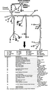
The 92-93 cars used the 91 wiring colors with the fuel pump under the hood near the A/C WOT relay:
Diagram courtesy of Tmoss & Stang&2birds
Diagram of 92-93 Mustang main wiring harness

The original 86-90 model cars used the fuel pump relay under the seat and different wiring colors for the wiring.
The 91 cars used a different wiring colors with the fuel pump relay mounted under the seat.
The 92-93 cars used the 91 wiring colors with the fuel pump under the hood near the A/C WOT relay:
Diagram courtesy of Tmoss & Stang&2birds
Diagram of 92-93 Mustang main wiring harness
Attachments
okay i see what u mean. use the realy under the hood and source everything to it. i teated it and some of it works. i have constant power and 12ac power. when i jump it it dont run but that might be the other half of the harness. the fuel pump power is hooked up to the one inside. when i jump it the relay under the hood clicks. so trace the wires but use the unde rthe hood one. i bet everything is there but the power to the pump. red wire
Rewiring everything to make the relay under the seat is probably not a good plan.
The relay under the hood clicks when you jumper the test ground because that is the one tied into the test circuit. It is probably the one that is tied into the computer control as well. That is a good thing, since it is supposed to work that way.
Remove the test jumper from the fuel pump self test. Then put the computer into test mode to dump the codes. You should hear the under the hood relay click when you turn the ignition switch to the Run position.
I recommend that you print out the fuel pump test path that I posted eariler and go through it one step at a time. If you are not skilled with electrical stuff, find somone who is to help you. Using that information to troubleshoot the relay under the hood will get it working in short order.
welp i got it wired to the relay under the seat and it works good but now when i went to check for spark i did have power on red/green but when i jumped the solenoid to check for spark on the tan wire. now my pump run all the time and i have no power to green and red. what should i do
Similar threads
- Replies
- 7
- Views
- 123
- Replies
- 4
- Views
- 97
- Replies
- 43
- Views
- 692
- Replies
- 1
- Views
- 202