Drum brake tips
There are two different shoes for the rear brakes. There is a long shoe, (secondary) & a short shoe (primary). The short shoe always faces on the front of the car.
One of the best things you can do is get a can of non-flammable brake parts cleaner & spray down the all the parts. Then blow everything off as clean as you can get it and take several photos of the intact brake before you disassemble it.
The rest of this is done from memory, so I may miss something.
Special tools needed: these are available at your local auto parts store.
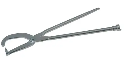
Brake spring pliers
Brake retainer remover
Big pair of diagonal cutter pliers
1.) Jack the car, placing it on jack stands.
2.) Remove the wheels, taking care not to lose the lug nuts. Some wheels may use a special lug nut that requires a security key. Locate the security key and make sure it fits BEFORE you put the car up on jack stands.
3.) Remove the brake drums. Sometimes the shoes will wear a lip on the inside of the drum that will make the drums difficult to remove. In that case you get to try & unadjust the shoes.
4.) The brake spring pliers have a socket on one leg that has a peg on it. That socket fits on the post at the top of the brake assembly. Once the socket end is firmly seated on the post, you can twist the brake spring pliers to lift the spring ends off the post. Remove both springs, and the hardware behind them. This is where the digital camera comes in handy. There is a self adjuster cable mechanism that is somewhat tricky to get back in the proper order and location. There is a small cable with a lug that fits over the post. It runs past the shoe retainer pins and finally to the self adjuster lever.
5.) Remove the retainer caps that hold the brake shoes in place. This is done by pressing in on the handle of the brake retainer tool so that it compresses the spring and then turn the tool to release the pins. Note the position of the previously mentioned cable, adjuster arm lever and guide.
6.) Once the brake shoe retainers are off the shoes can be removed from their mounts. The E brake cable is pushed by using the dikes between the fork and the cable connects to the shoes. Push the spring back until the cable can be slid out of the fork.
That’s how to take them apart. When I return, I’ll try to post on how to put them back together.
Brake Shoes
Tools Required:
l Brake Cylinder Clamp D81L-1103-B
l Brake Shoe R and R Spring BT-11
Removal
1. With the wheel and drum removed, install Brake Cylinder Clamp D81L-1103-B or equivalent over the ends of the brake cylinder.
2. Remove the shoe-to-anchor springs with Brake Shoe R and R Spring BT-11 or equivalent and unhook the cable eye from the anchor pin.
3. Remove the shoe guide (anchor pin) plate.
4. Remove the shoe hold-down springs, shoes, adjusting screw, pivot nut, socket and automatic adjustment parts.
5. Remove the parking brake link, spring and retainer. Disconnect the parking brake cable from the parking brake lever.
6. After removing the rear brake secondary shoe, disassemble the parking brake lever from the shoe by removing the retaining clip and spring washer.
Installation
Before installing the rear brake shoes, assemble the parking brake lever to the secondary shoe and secure it with the spring washer and retaining clip. A tang on the parking brake lever engages the secondary shoe on 228.6mm (9 inch) brakes.
2. Apply a light coating of Disc Brake Caliper Slide Grease D7AZ-19590-A (ESA-M1C172-A) or equivalent at the points where the brake shoes contact the backing plate. Be careful not to get any lubricant on the brake linings.
3. Position the brake shoes on the backing plate. The primary shoe with the short lining faces toward the front of the vehicle. The secondary shoe (long lining) faces rearward. Secure the assembly with the hold-down springs. Install the parking brake link, spring and retainer. Back-off the parking brake adjustment; then, connect the parking brake cable to the parking brake lever.
4. Install the shoe guide (anchor pin) plate on the anchor pin.
5. Place the cable eye over the anchor pin with the crimped side toward the drum.
6. Install the primary shoe to anchor spring (green on 228.6mm (9 inch) brake).
7. Install the cable guide on the secondary shoe web with the flanged hole fitted into the hole in the secondary shoe web. Thread the cable around the cable guide groove. It is imperative that the cable be positioned in this groove and not between the guide and the shoe web.
8. Install the secondary shoe-to-anchor spring (white on 228.6mm (9 inch) brakes). Be certain that the cable eye is not cocked or binding on the anchor pin when installed. All parts should be flat on the anchor pin.
9. Remove the brake cylinder clamp after both shoe-to-anchor springs have been installed.
10. Apply a thin, uniform coat of Premium Long-Life Grease XG-1-C or equivalent to the threads and the socket end of the adjusting screw. Turn the adjusting screw into the adjusting pivot nut to the limit of the threads, and then back-off one-half turn.
Interchanging the brake shoe adjusting screw assemblies from one side of the vehicle to the other would cause the brake shoes to retract rather than expand each time the automatic adjusting mechanism operated. To prevent installation on the wrong side of the vehicle, the socket end of the adjusting screw is stamped R or L.
11. Place the adjusting socket on the screw and install this assembly between the shoe ends with the adjusting screw toothed wheel nearest the secondary shoe.
12. Hook the cable hook into the hole in the adjusting lever. The adjusting levers are stamped R or L to indicate their installation on RH or LH brake assembly.
13. Position the hooked end of the adjuster spring completely into the large hole in the primary shoe web. Connect the loop end of the spring to the adjuster lever hole.
14. Pull the adjuster lever, cable and automatic adjuster spring down and toward the rear, engaging the pivot hook in the large hole of the secondary shoe web.
15. After installation, check the action of the adjuster by pulling the cable between the cable guide and the adjuster lever toward the secondary shoe web, far enough to lift the lever past a tooth on the adjusting screw wheel. The lever should snap into position behind the next tooth, and the release of the cable should cause the adjuster spring to return the lever to its original position. This return action of the lever will turn the adjusting screw one tooth.
If pulling the cable does not produce the action described, or if the lever action is sluggish instead of positive and sharp, check position of lever on the adjusting screw toothed wheel.
With the brake in a vertical position (anchor at the top), the lever should contact the adjusting wheel 4.763mm ± .794mm (3/16 inch ± 1/32 inch) above the centerline of the screw. If the contact point is below this centerline, the lever will not lock on the teeth in the adjusting screw wheel, and the screw will not be turned.
Perform brake shoe adjustment.
To determine the cause of this condition:
a. Ensure that the upper or anchor pin end of the cable is pulled toward the cable guide as far as possible and that the end fitting is pointing toward the cable guide.
b. Check the cable end fittings. The cable should completely fill or extend slightly beyond the crimped section of the fittings. If it does not meet this specification, possible damage is indicated, and the cable assembly should be replaced.
c. Check the cable length. Measure from the inside edge of the hook to the far edge of the anchor hole. The cable length for 228mm (9 inch) brakes is 214.31mm (8.438 inches). The tolerance on cable length is± 0.397mm (1/64 inch).
d. Check the cable guide for damage. The cable groove should be parallel to the shoe web, and the body of the guide should lie flat against the web. Replace the guide if it shows damage.
e. Check the pivot hook on the lever. The hook surfaces should be square with the body of the lever for proper pivoting. Replace the lever if the hook shows damage.
f. Verify that the adjusting screw socket is properly seated in the notch in the shoe web.
NOTE:
Whenever rear brake linings are removed, the parking brake cable tension should be checked. Refer to «Section 06-05» and adjust as required.
16. Ensure that the upper ends of the brake shoes are seated against the anchor pin, and that the shoes are centered on the backing plate. If they are not seated, back-off the parking brake system adjustment to obtain 0.127 to 0.64mm (0.005 to 0.025 inch) play after overcoming the load of the parking brake link spring.


 RIP
RIP