Save yourself time and money. Do the checklist as recommended...
Cranks OK, but No Start Checklist for Fuel Injected Mustangs
Revised 14-Sept-2008 to add warning about over fusing circuits
All text applies to all models unless stated otherwise.
Note: 94-95 specific changes are in red
1.) Remove push on connector (small red/blue wire) from starter solenoid and turn ignition switch on. Place car in neutral or Park and set the parking brake. Remove the coil wire from distributor & and hold it 3/8” away from the engine block. Jumper the screw to the big bolt on the starter solenoid that has the battery wire connected to it. You should get a nice fat blue spark.
Most of the items are electrical in nature, so a test light, or even better, a voltmeter, is helpful to be sure they have power to them.
No spark, possible failed items in order of their probability:
A.) MSD or Crane ignition box if so equipped
B.) Coil
C.) TFI module
D.) PIP sensor in distributor. The PIP sensor supplies the timing pulse to trigger the TFI and injectors. See paragraph 5A - a noid light will tell if the pip is working by flashing when the engine is cranking.
E.) No ECC or computer power - ECC or computer relay failure
86-93 models only: ECC relay next to computer - look for 12 volts at the fuel injector red wires
94-95 models only: EEC or PCM power relay in the constant control relay module. Look for 12 volts at the fuel injector red wires.
F.) No ECC or computer power - fuse or fuse link failure
86-93 models only: Fuse links in wiring harness - look for 12 volts at the fuel injector red wires. All the fuse links live in a bundle up near the starter solenoid.
94-95 models only: 20 amp EEC fuse in the engine compartment fuse box. Look for 12 volts at the fuel injector red wires.
G.) Ignition switch - look for 12 volts at the ignition coil red/lt green wire. No 12 volts, blown fuse link or faulty ignition switch. Remove the plastic from around the ignition switch and look for 12 volts on the red/green wire with the switch in the Run position. No 12 volts and the ignition switch is faulty. If 12 volts is present in the Run position, then the fuse or fuse link is blown.
Note: fuses or fuse links blow for a reason. Don’t replace either a fuse or fuse link with one with a larger rating than stock. Doing so invites an electrical fire.
Ignition fuse links may be replaced with an inline fuse holder and 5 amp fuse for troubleshooting purposes.
94-95 models only: Check inside fuse panel for fuse #18 blown – 20 amp fuse
H.) Bad or missing secondary power ground. It is located between the back of the intake manifold and the driver's side firewall. It supplies ground for the alternator, A/C compressor clutch and other electrical accessories such as the gauges.
I.) Missing or loose computer power ground. The computer has its own dedicated power ground that comes off the ground pigtail on the battery ground wire. Due to it's proximity to the battery, it may become corroded by acid fumes from the battery. It is a black cylinder about 2 1/2" long by 1" diameter with a black/lt green wire. You'll find it up next to the starter solenoid where the wire goes into the wiring harness
J.) Computer
K.) Engine fires briefly, but dies immediately when the key is released to the Run position. Crank the engine & when it fires off, pull the small push on connector (red wire) off the starter relay (Looks like it is stuck on a screw). Hold the switch in the crank position: if it continues to run there is a problem with either the ignition switch or TFI module. Check for 12 volts at the red/green wire on the coil with the switch in the Run position. Good 12 volts, then replace the TFI. No 12 volts, replace the ignition switch.
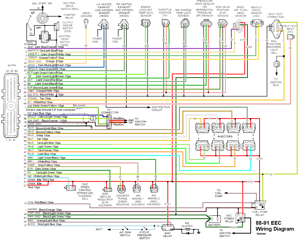
See the following links for wiring diagrams...
AutoZone.com | Vehicle Selection - Year for 79-88 model Mustangs
Computer/fuel pump/ignition wiring diagram, 86 model
http://www.autozone.com/images/cds/gif/large/0900823d80167158.gif
Computer/fuel pump/ignition wiring diagram, 87 model
http://www.autozone.com/images/cds/gif/large/0900823d8016715e.gif
Ignition wiring diagram, 87 model
http://www.autozone.com/images/cds/gif/large/0900823d8016715f.gif
Computer/fuel pump wiring diagram, 88 model
http://www.autozone.com/images/cds/gif/large/0900823d80167162.gif[
Ignition wiring diagram, 88 model
http://www.autozone.com/images/cds/gif/large/0900823d80167163.gif
AutoZone.com | Vehicle Selection - Year for 89-93 model Mustangs
Computer/fuel pump/ignition wiring diagram, 89-90 cars
http://www.autozone.com/images/cds/gif/large/0900823d8019595f.gif
Computer/fuel pump/ignition wiring diagram, 91-93 cars
http://www.autozone.com/images/cds/gif/large/0900823d80195960.gif
http://www.autozone.com/servlet/UiBroker?ForwardPage=/az/cds/en_us/0900823d/80/1d/db/3c/0900823d801ddb3c.jsp for 94-98 model cars
2.) Spark at coil wire, pull #1 plug wire off at the spark plug and check to see spark. No spark, possible failed items in order of their probability:
A.) Moisture inside distributor – remove cap, dry off & spray with WD40
B.) Distributor cap
C.) Rotor
D.) Spark Plug wires
E.) Coil weak or intermittent - you should see 3/8" fat blue spark with a good coil
3.) Spark at spark plug, but no start.
Next, get a can of starting fluid (ether) from your local auto parts store: costs a $1.30 or so. Then pull the air duct off at the throttle body elbow, open the throttle, and spray the ether in it. Reconnect the air duct and try to start the car. Do not try to start the car without reconnecting the air duct.
Two reasons:
1.) If it backfires, the chance for a serious fire is increased.
2.) On Mass Air cars, the computer needs to measure the MAF flow once the engine starts.
If it starts then, you have a fuel management issue. Continue the checklist with emphasis of fuel related items that follow. If it doesn’t, then it is a computer or timing issue: see Step 4.
Clue – listen for the fuel pump to prime when you first turn the ignition switch on. It should run for 5-20 seconds and shut off. To trick the fuel pump into running, find the EEC test connector and jump the connector in the Upper RH corner to ground. The EEC connector is near the wiper motor and LH hood hinge.
If the relay & inertia switch are OK, you will have power to the pump. Check fuel pressure – remove the cap from the schrader valve behind the alternator and depress the core. Fuel should squirt out, catch it in a rag. Beware of fire hazard when you do this. In a pinch, you can use a tire pressure gauge to measure the fuel pressure. It may not be completely accurate, but you will have some clue as to how much pressure you have. If you have any doubts about having sufficient fuel flow/pressure, rent a fuel pressure test gauge from the auto parts store. That will tell you for sure if you have adequate fuel pressure.
4.) No fuel pressure, possible failed items in order of their probability:
A.) Tripped inertia switch – Coupe & hatch cars hide it under the plastic trim covering the driver's side taillight. Use the voltmeter or test light to make sure you have power to both sides of the switch
B.) Fuel pump power relay – located under the driver’s seat in most stangs built before 92. On 92 and later model cars it is located below the Mass Air Flow meter. Look for 12 volts at the Pink/Black wire on the fuel pump relay.
C.) Clogged fuel filter
D.) Failed fuel pump
E.) 86-90 models only: Blown fuse link in wiring harness. Look for 12 volts at the Orange/Lt Blue wire on the fuel pump relay.
91-93 models only Blown fuse link in wiring harness. Look for 12 volts at the Pink/Black wire on the fuel pump relay.
The fuse links for all model years 86-93 live in the wiring harness near the starter solenoid.
94-95 models only: 20 amp fuel pump fuse in the engine compartment fuse box. Look for 12 volts at the Dark green/yellow wire on the constant control relay module.
F.) Engine seem to load up on fuel and may have black smoke at the tailpipe. Fuel pressure regulator failed. Remove the vacuum line from the regulator and inspect for fuel escaping while the pump is running. If fuel is coming out the vacuum port, the regulator has failed. Check the regulator vacuum line for fuel too. Disconnect it from the engine and blow air though it. If you find gas, the regulator has failed.
5.) Fuel pressure OK, the injectors are not firing.
A.) A noid light available from any auto parts store, is one way to test the injector wiring.
The noid light plugs into the fuel injector harness in place of any easily accessible injector. Plug it in and it will flash if the injector is firing.
B.) I like to use an old injector with compressed air applied to the injector where the fuel rail would normally connect. I hook the whole thing up, apply compressed air to the injector and stick it in a paper cup of soapy water. When the engine cranks with the ignition switch on, if the injector fires, it makes bubbles. Cheap if you have the stuff laying around, and works good too.
D.) Pull an injector wire connector off and look for 12 volts on the red wire when the ignition switch is on.
E.) No power, then look for problems with the 10 pin connecter (salt & pepper shakers at the rear of the upper manifold).
F.) No power and the 10 pin connections are good: look for broken wiring between the orange/black wire on the ECC relay and the red wire for the 10 pin connectors.
G.) TPS voltage exceeds 3.7 volts with the throttle closed. This will shut off the injectors, since the computer uses this strategy to clear a flooded engine. Use a DVM, a pair of safety pins, and probe the black/white and green wires to measure the TPS voltage.
On a 94-95 Mustang, probe the black/white and grey/white wires to measure the TPS voltage.
It should be .5-.99 volts with the key on, engine not running. Note that if the black/white wire (signal ground) has a bad connection, you will get some strange readings. Make a second measurement using the battery post as the ground to eliminate any ground problems. If the readings are different by more than 5%, you may have a high resistance condition in the black/white signal ground circuit.
6.) Spark & fuel pressure OK.
A.) Failed IAB or improperly set base idle (no airflow to start engine). Press the throttle ¼ way down and try to start the car. See the "
Surging Idle Checklist for help with all your idle/stall problems.
B.) Failed computer (not very likely)
C.) Engine ignition or cam timing off: only likely if the engine has been worked on recently).
D.) Firing order off: HO & 351 use a different firing order from the non HO engines.
HO & 351W 1-3-7-2-6-5-4-8
Non HO 1-5-4-2-6-3-7-8
E.) No start when hot - Press the throttle to the floor & try starting it if you get this far. If it starts, replace the ECT.
F. ) Engine that has had the heads off or valves adjusted. Do a compression test to make sure the valves are not adjusted too tight. You should have a minimum of 90 PSI on a cold engine.