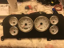
Guage Cluster

rotorhead22

Active Member
Dec 17, 2020
175
89
38
Wesley Chapel, Florida
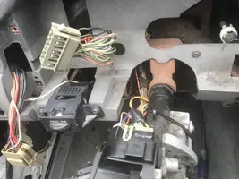
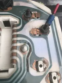
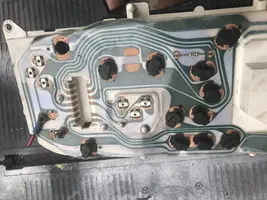
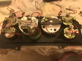
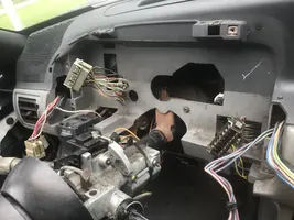
And the fun just keeps on coming. I discovered that my alternator upgrade wasnt work and following the troubleshooting chart that is posted on Stangnet, I removed the guage cluster to find a complete mess of burnt copper ribbon and what not. So I guess the car is telling me to install the new cluster from New Vintage gauges. Better than fuel problems.
 

Attachments

  • IMG_7500.webp
    IMG_7500.webp
    223.3 KB · Views: 181
  • IMG_7503.webp
    IMG_7503.webp
    123.2 KB · Views: 158
  • IMG_7504.webp
    IMG_7504.webp
    220.4 KB · Views: 175
  • IMG_7505.webp
    IMG_7505.webp
    146.8 KB · Views: 184
  • IMG_7506.webp
    IMG_7506.webp
    316 KB · Views: 176
  • IMG_7507.webp
    IMG_7507.webp
    225.5 KB · Views: 174
Definitely a wiring mess back there.

You can repair the ribbon cable by soldering a jumper. If it's busted in a few spots, buy a used 4 cyl cluster from the same year span. You can use the ribbon cable off that. Other than the tach and speedometer it's the same stuff. Nice to have some spare components as well.

Of course, the other wires needs to be fixes as well such as that loose white wire. Who knows what the red wire tapped into the voltage pin on the reverse was being used for
 
  • Like
Reactions: rotorhead22
So after studying the wire schematic for the stock cluster panel I am left scratching my head as to why the red/light green coil wire is connected to the cluster panel? I know that I need to jump the green/red wire for the alternator but why the coil connection
 
So after studying the wire schematic for the stock cluster panel I am left scratching my head as to why the red/light green coil wire is connected to the cluster panel? I know that I need to jump the green/red wire for the alternator but why the coil connection
the pinouts are different form 87 to 89 and 90 to 93 . When I did mine on my 90 i think i jumped 2 to 14 on the passenger side.. 87 to 89 jump 5 to 6 on the driver side connector. #5 is the coil/batt pin. If memory serves me right its a 50ohm? resistor inline to simulate the check engine light resistance.

1624406660718.webp


1624406680998.webp
 
So after connecting the light green/red and the red/green wires I discovered that my 3g alternator wasn't charging and after a few days of multimeter work I found out that the new voltage regulator was fried. The money pit got deeper :banana:

You have to put a resistor between the two wires; can't just be connected. If you look at the printed circuit on your factory instrument cluster there should be a resistor on the alternator circuit. That's to bypass the light bulb if it blows so that your alternator continues to charge. Just rip that resistor out of the printed circuit and use it. If you didn't have a resistor there, it's possible that's what caused your voltage regulator to fail.

Kurt
 
  • Like
Reactions: rotorhead22