Help with RF cobra 75.

First off thanks for having me! I have a 90 lx/get conversion. Ron Francis wiring loom instructions are lacking in many ways.
But my problem is the two eight pin connectors near brake booster. And where they go to through the car? Thought I ought a stand alone harness. Can't seem to get spark to TFI. And all things are new. Pump (fuel) all sensors . Dizzy, my ignition switch has been replaced but wiring has me baffled. Couple different wire colors. A full car wiring diagram would be awesome! Anyone done this swap before.? Tyis Thanks for ANY input
 
  • Sponsors (?)


First off thanks for having me! I have a 90 lx/get conversion. Ron Francis wiring loom instructions are lacking in many ways.
But my problem is the two eight pin connectors near brake booster. And where they go to through the car? Thought I ought a stand alone harness. Can't seem to get spark to TFI. And all things are new. Pump (fuel) all sensors . Dizzy, my ignition switch has been replaced but wiring has me baffled. Couple different wire colors. A full car wiring diagram would be awesome! Anyone done this swap before.? Tyis Thanks for ANY input
I put a TDZ in a F250 w/408 stroker....IT IS A STAND ALONE HARNESS.

Theres like 5 wires for hookup...You have battery power connection that gets connected to the battery also a hot positive wire that comes from the column switch or from the positive on the coil..

You also have a fuelpump wire and a negative from the ECU wiring that needs and has to be grounded to the cylinder head and you also have to make sure the dizzy is grounded good to the engine block too......

Then you have a purple wire that hooks to the same wire that triggers your starter solenoid...This purple wire is a wire that retards the spark for ease of startup.Thas why I had to run a diode suppressed solenoid because the flyback from the solenoid going back through the purple wire into the TFI moduule was frying TFI modules every week..

Good Luck
Thank you that's the most concise explanation of TFI I've heard. It made me dizzy one or two days before I learned it but honestly I don't teach it because I can't articulate what happens like that yet. Well put. It turned over with a different TFI that ford made. It accepted the IDM wire as a coil ground. Jury is still out but I have spark and it's able to run. Been a long bit and feel the oil pump is taking it's time flowing oil so valves aren't lifting fully. I'll keep posting , right now I have high idle . Could be just cable adjust them , take out dizzy and spin oil pump till all the rockets get wet. Then drop in the distributor it's at confirmed tdc. It will smooth out. It's a horrible noise it makes you get pressure with an impact drill is Way easier.
 
I put a TDZ in a F250 w/408 stroker....IT IS A STAND ALONE HARNESS.

Theres like 5 wires for hookup...You have battery power connection that gets connected to the battery also a hot positive wire that comes from the column switch or from the positive on the coil..

You also have a fuelpump wire and a negative from the ECU wiring that needs and has to be grounded to the cylinder head and you also have to make sure the dizzy is grounded good to the engine block too......

Then you have a purple wire that hooks to the same wire that triggers your starter solenoid...This purple wire is a wire that retards the spark for ease of startup.Thas why I had to run a diode suppressed solenoid because the flyback from the solenoid going back through the purple wire into the TFI moduule was frying TFI modules every week..

Good Luck
I would still like to know why the wire that is for data to ecu uses what is the important ground you speak of being needed for dizzy. Because I've never seen it grounded any other way ? Thanks for any input
 
First off thanks for having me! I have a 90 lx/get conversion. Ron Francis wiring loom instructions are lacking in many ways.
But my problem is the two eight pin connectors near brake booster. And where they go to through the car? Thought I ought a stand alone harness. Can't seem to get spark to TFI. And all things are new. Pump (fuel) all sensors . Dizzy, my ignition switch has been replaced but wiring has me baffled. Couple different wire colors. A full car wiring diagram would be awesome! Anyone done this swap before.? Tyis Thanks for ANY input

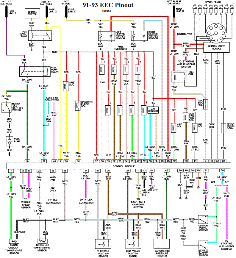
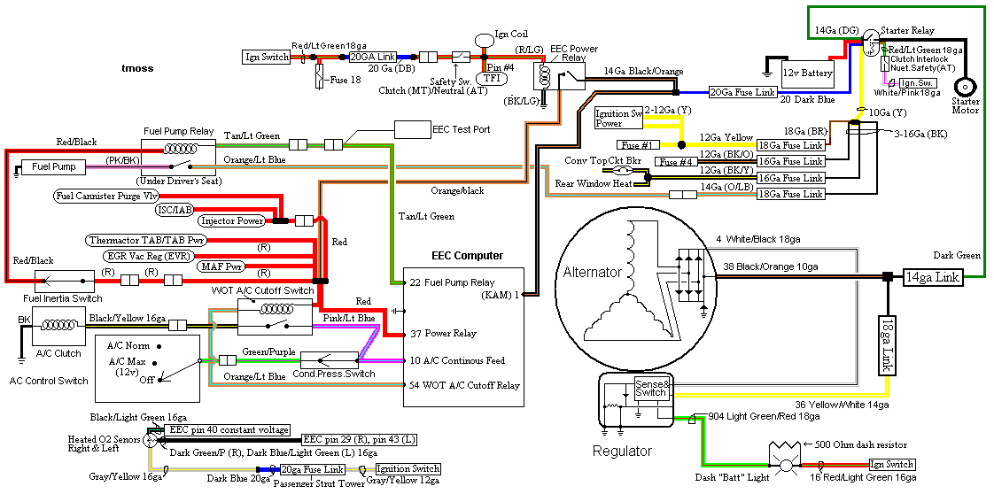
The following are diagrams courtesy of Tmoss & Stang&2birds

Complete computer, actuator & sensor wiring diagram for 91-93 Mass Air Mustangs
91-93_5.0_EEC_Wiring_Diagram.gif


5.0 wiring diagram for Fuel Injectors, Sensors, and Actuators
fuel-alt-links-ign-ac.gif


See the following website for some help from Tmoss (diagram designer) & Stang&2Birds (website host) for help on 88-95 wiring; http://www.veryuseful.com/mustang/tech/engine/ Everyone should bookmark this site.[/b]

TFI module wiring for 94-95 Mustang GT
http://www.veryuseful.com/mustang/tech/engine/images/Mustang-94-95-IgnitionControlModule.gif

Complete computer, actuator & sensor wiring diagram for 94-95 Mustangs

Complete computer, actuator & sensor wiring diagram for 91-93 Mass Air Mustangs

Complete computer, actuator & sensor wiring diagram for 88-90 Mass Air Mustangs

5.0 wiring diagram for Fuel Injectors, Sensors, and Actuators

Main body EFI wiring harness

Ignition switch wiring

O2 sensor wiring harness

Vacuum diagram 89-93 Mustangs

HVAC vacuum diagram

TFI module differences & pin out

Fuse box layout

Mustang 5.0 Lights and Radio schematic, by TMoss:
http://www.veryuseful.com/mustang/tech/engine/images/mustangFoxLights-Radio_diag.gif

87-92 power window wiring

93 power window wiring

T5 Cutaway showing T5 internal parts

Visual comparison of the Ford Fuel Injectors, picture by TMoss:

Convertible top motor wiring http://www.veryuseful.com/mustang/tech/engine/images/mustang88VertTopMotorCkt.gif

Engine mounted fuel injector harness

Location of the TPS, IAB, and the 10-pin connectors on a 5.0, picture by TMoss:

Starter circuit

Alternator diagram for 94-95 Mustangs.
 
  • Useful
Reactions: 1 user
I would still like to know why the wire that is for data to ecu uses what is the important ground you speak of being needed for dizzy. Because I've never seen it grounded any other way ? Thanks for any input
Alls I stated was make sure your dizzy is properly grounded...My engine block was painted in the groove that the distributor rests on , my billet dizzy was clearcoated, the holddown was powdercoated and the screw I used was Anodized steel and we all know anodize , powdercoat and paint stops anything from grounding.....

If its not cranking Id look at the transmission portion especially the transmission plug if using an automatic transmission or even an automatic transmission ECU and a manual transmission..............

 
Last edited:
I would still like to know why the wire that is for data to ecu uses what is the important ground you speak of being needed for dizzy. Because I've never seen it grounded any other way ? Thanks for any input
What I do to make sure everything is grounded properly is take my DVOM and put it on continuity tester then hook one side to the battery negative and then I touch the alternator body , starter body , the brass portion of the coolant temp sensor and the air temp sensor and the distributor housing now ever since having a problem related to a distributor that wasnt grounded due to a painted block , a clearcoated billet aluminum distributor, a powdercoated holdown and an anozided steel screw stopping the distributor from properly grounding....

The Important ground wire is the single ground wire coming from the harness....It should be a stand alone grounding and placed on the rear of the cylinder head...It doesnt matter which head,,,,,Dont stack any other grounds up on this screw with the ECU grounding wire.......!

The only other thing is selecting the proper jumper wire for whether youre utilizing a stickshift or automatic transmission too and that dictates whether youll need an interface wire for your 02 sensors as theres differences in the computers between auto and stickshifts and the 02 sensor harnesses and how theyre pinned out...An auto computer will work with a stickshift but it still needs to be piunned out as an automatic and have the proper wiring for the 02 sensors...If you use an auto computer but select stickshift trans strategy its not gonna work.....

You need to select auto and have the proper 02 interface wires like these...... https://www.summitracing.com/parts/...1321357541559&utm_content=GSAPI+5ba2972b8192cf

And I dont know what you mean by data wire....Theres a 5 wire hookup like I stated...none stated data but one stated it retarded the distributor for ease of startup and goes on the starter trigger lead that triggers the starter solenoid when the keyswitch is turned to crank it up.....

Ford engines labor hard when restarting up hot so Ron Francis added a purple wire that runs back to the TFI module that gives the TFI module a lil power burst that retards the timing so the engine starts up labor free.....Without a diode protected starter solenoid you will be replacing TFI modules left and right through a phenomenon called FLYBACK....look it up....If your starter solenoid doesnt have a sticker that says diode suppressed its not diode protected against flyback..

s-l1600 (14).jpg


Last week I took my whole harness out of my truck again to do away with their BS relay block system and hooked everything straight to the computer and only 2 relays like FORD did but diode protected ones........

IMG_20211221_152641.jpg


I thought I had the whole thing straightened out by adding diode protected relays to control flyback and they worked as intended but....

I was getting running glitches when I hit hard bumps in the highway and found out if I even slightly wiggled the relays while the truck was running changed the way it idled and it even stalled once too so using a similar diagram as posted by another member above I just did away with the relays where I had to and now my truck is running [knock on wood] a ton better as the BS terminals Ron Francis uses has no true clamping force on the terminals and over a short period of time loses its grip and even using a pick tool to tighten them up does very little to offer a long term fix as its still temporary and depending on how much you drive your vehicle is how much you will be pulling relays and tightening up the cheap chinese lugs as the relays get quite hot while in constant operation and the wires wiggle too much inside the terminal housings to offer any clamping support..............

Oh and I also had to do away with their BS 4 fuse - fuse holder aswell as they werent grabbing the fuses good either and the way the power was distributed was quite wrong..................On Fords diagram the majority of the systems that RF seperated and seperately fused run off the same main wires coming off the ECU hooked to #37 & 57 which are also hooked together so thats the way theyre hooked up in my harness now...Theres seperated 02 sensor power and grounds that werent connected to the ECU correctly either....

Screenshot 2022-10-03 122937.jpg


These are the diagram I used....Theyre not mine and I take no credit for theyre existence ...


1664815906641.png


Last edited:
What I do to make sure everything is grounded properly is take my DVOM and put it on continuity tester then hook one side to the battery nagative and then I touch the alternator ,starter ,brass portion of coolant temp sensor and air temp sensor the the distributor housing now ever since having a problem related to a distributor that wasnt grounded due to a painted block , a clearcoated billet aluminum distributor, a powdercoated holdown and an anozided steel screw stopping the distributor from properly grounding....

And I dont know what you mean by data wire....Theres a 5 wire hookup like I stated...none stated data but one stated it retarded the distribitor for ease of startup and goes on the starter trigger lead that triggers the starter solenoid .....

Ford engines lanor hard when hot when starting up Ron Francis added a purple wire that runs back to the TFI module that gives the TFI module a lil power burst that retards the timing so the engine starts up labor free.....Without a diode protected starter solenoid you will be replacing TFI modules left and right through a phenomenon called FLYBACK....look it up....If youre solenoid doesnt have a sticker that says diode suppressed its not diode protected against flyback..

s-l1600 (14).jpg


Last week I had to take my whole harness out of my truck again to do away with their BS relay block system and hooked everything straight to the computer and only 2 relays like FORD did but diode protected ones........

I was getting running glitches when I hit hard bumps in the highway and found out of you even slightly wiggled the relays while the truck was running changed the way it idled and it even stalled once too so using a similar diagram as posted by another member above I just did away with the relay where I had to and now my truck is running [knock on wood] a ton better as the BS terminals Ron Francis uses has no true clamping force on the terminals and over a short period of time loses its grip and even using a pick tool to tighten them up does very little to offer a long term fix as its still temporary and depending on how much you drive your vehicle is how much youll be pulling relays and tightening up the cheap chinese lugs as the relays get quite hot while in constant operation..............
Good info ! I have heard about the diode relays. They are the white ones. I heard they stop the problem with blowing yfi modules ..