homemade MILS

Stang|ess

seeking cyber partner(s)
Oct 18, 2003
941
0
37
Hawaii
scem.gif


Can someone explain this to me?

The PC board is quite large, so I'm assuming I can cut it into a 2x2 square?

I will refer to each point like so:

1 2
3 4

In hole 1, there will be 1 end of the resistor, capacitor, and the gray wire all together? And what's that line from holes 3 to 4. And Finally, what do I do with the pc board terminals?

Thanks in advance :D
 

Attachments

  • scem.gif
    scem.gif
    25.6 KB · Views: 518
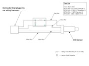
I used this diagram to make mine, but I didn't use the PC board or connectors.

Basically, go to Radio Shack and buy the parts minus the PC board and it might start to make a little more sense. The diagram shows where the parts go in relation to the wires dont really get too caught up in it. I just cut the wires and soldered them back together.

Here is what you REALLY need.

Radio Shack # 2721434 (x2)
Radio Shack # 2711356 (comes in 5 pack)
Black electrical tape
Heat Shrink Tubing (optional, but makes it look a lot better)
Soldering Iron
Wire cutters/strippers
Lighter or heat gun

I think it cost me a total of $6.24 for the 3 itmes from Radio Shack (2721434s, 2711356, and the heat shrink tubing).

I think I have some pictures at home from where I did mine, if I can find them, I will do a step by step write up on how I did it. Havent had a problem with mine in about 6k miles.

Hope this helped.

J
 
Thanks, I realized that I don't need the board or the pc board terminals, and I can solder the resistor and capacitor inline with the wires. Too bad I bought everything already, but it's only a few dollars.

I bought the 2 capacitors, but it seems that they're too resistive. I bought the right part number, but the wrong part was inside.
 
Might I also make the suggestion you use a 1/2 watt resistor and not the 1/4 watt. Some people experience problems with the 1/4 watt not getting them low enough readings for the computer.