idles poorly and can backfire until warmed up

7991LXnSHO

wanna catch the space herp
10 Year Member
Sep 1, 2010
7,388
3,099
194
Kearney, NE
When cold, my 91 5.0 can backfire out the exhaust and it idles poorly until warmed up a few blocks. This is worse in the cold. This is a former drag car being returned to the street. The EGR is somehow deactivated (it has a relay with a resistor under the dash and no coolant hoses to the egr plate), but I do not know what else is gone. The cam is a FMS "b" or "E" cam, x pipe, super turbos mufflers, idles at about 1000 rpm when warm. It has some head and intake porting. I'd like to get this fixed before I go with further mechanical modifications. It also smells rich when I park it back in the garage after driving. What steps should I follow to help this?
1. check throtle voltage 2. clean IAC 3. then what???:shrug:
 
  • Sponsors (?)


See the "Surging Idle Checklist for help with all your idle/stall problems.

The quick and easy way to dump the codes is in there too, and all you need to do it is a paper clip! The first two posts contain all the updates to the fixes. At last count there were 24 possible causes and fixes for surging idle/stall problems. I continue to update it as more people post fixes or ask questions.
 
Idle does not surge, will read, EGR question too

Thank you for the link. I did not check out the strand first since the idle does not surge (although I have read and printed it out it when I first joined). It just idles like "junk" until it is warmed up a little. I will read the strand again, and I do have a new code reader to use. I already have a replacement vac hose diagram specific to my model's emissions code since the one in the engine bay is long gone.

Any other ideas specific to the problem?

I'll ask again, does the aftermarket relay and resistor under the dash sound like how the computer is being sent the EGR signal although it is deactivated somehow???
 
There is no relay in th stock EGR system, and no external resistor. The only resistor in a stock system is the EGR sensor: anything else is either another circuit or some aftermarket gizmo that may or may do anything for the EGR.

Some basic theory to clarify how things work is in order…

EGR System theory and testing

The EGR shuts off at Wide Open Throttle (WOT), so it has minimal effect on performance. The addition of exhaust gas drops combustion temperature, increases gas mileage and reduces the tendency of the engine to ping. It can also reduce HC emissions by reducing fuel consumption. The primary result of EGR usage is a reduction in NOx emissions.

The EGR system has a vacuum source (line from the intake manifold) that goes to the EVR, computer operated electronic vacuum regulator. The EVR is located on the back of the passenger side shock strut tower. The computer uses RPM, Load. and some other factors to tell the EVR to pass vacuum to open the EGR valve. The EGR valve and the passages in the heads and intake manifold route exhaust gas to the EGR spacer (throttle body spacer). The EGR sensor tells the computer how far the EGR valve is open. Then computer adjusts the signal sent to the EVR to hold, increase or decrease the vacuum. The computer adds spark advance to compensate for the recirculated gases and the slower rate they burn at.


attachment.php


Troubleshooting:
There should be no vacuum at the EGR valve when at idle. If there is, the EVR (electronic vacuum regulator) mounted on the backside of the passenger side wheelwell is suspect. Check the vacuum line plumbing to make sure the previous owner didn’t cross the vacuum lines.

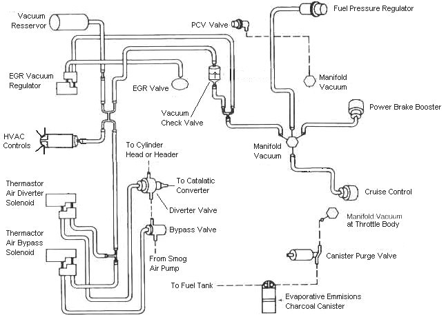
Diagram courtesy of Tmoss & Stang&2birds. (the diagram says 88 GT, but the EGR part is the same for 86-93 Mustangs)
88Stang5.0Vacuum.gif


The EGR sensor is basically a variable resistor, like the volume control on a radio. One end is 5 volt VREF power from the computer (red/orange wire). One end is computer signal ground (black/white), and the middle wire (brown/lt green) is the signal output from the EGR sensor. It is designed to always have some small voltage output from it anytime the ignition switch is the Run position. That way the computer knows the sensor & the wiring is OK. No voltage on computer pin 27 (brown/lt green wire) and the computer thinks the sensor is bad or the wire is broken and sets code 31. The voltage output can range from approximately .6-.85 volt.

The EVR regulates vacuum to the EGR valve to maintain the correct amount of vacuum. The solenoid coil should measure 20-70 Ohms resistance. The regulator has a vacuum feed on the bottom which draws from the intake manifold. The other vacuum line is regulated vacuum going to the EGR valve. One side of the EVR electrical circuit is +12 volts anytime the ignition switch is in the run position. The other side of the electrical circuit is the ground path and is controlled by the computer. The computer switches the ground on and off to control the regulator solenoid.


EGR test procedure courtesy of cjones

EGR test procedure courtesy of cjones

to check the EGR valve:
bring the engine to normal temp.

connect a vacuum pump to the EGR Valve or see the EGR test jig drawing below. Connnect the test jig or to directly to manifold vacuum.

Do not connect the EGR test jig to the EVR (Electronic Vacuum Regulator).


apply 5in vacuum to the valve. Using the test jig, use your finger to vary the vacuum

if engine stumbled or died then EGR Valve and passage(there is a passageway through the heads and intake) are good.

if engine did NOT stumble or die then either the EGR Valve is bad and/or the passage is blocked.

if engine stumbled, connect EGR test jig to the hose coming off of the EGR Valve.
Use your finger to cap the open port on the vacuum tee.
snap throttle to 2500 RPM (remember snap the throttle don't hold it there).
did the vacuum gauge show about 2-5 in vacuum?
if not the EVR has failed

EGR test jig
attachment.php


To test the computer and wiring to the computer, you can use a test light across the EVR wiring connectors and dump the codes. When you dump the codes, the computer does a self test that toggles every relay/actuator/solenoid on and off. When this happens, the test light will flicker. If the test light remains on the computer or the wiring is suspect.

To check the EVR to computer wiring, disconnect the EVR connector and connect one end of the Ohmmeter to the dark green wire EVR wiring. Remove the passenger side kick panel and use a 10 MM socket to remove the computer connector from the computer. Set the Ohmmeter to high range and connect the other ohmmeter lead to ground. You should see an infinite open circuit indication or a reading greater than 1 Meg Ohm. If you see less than 200 Ohms, the dark green wire has shorted to ground somewhere.

Late Model Restoration may still have the Ford Racing M-12071-N302 kit with the EGR valve & sensor along with the ACT & ECT sensors for $45. See http://www.latemodelrestoration.com/iwwida.pvx?;item?item_no=M12071N302 1&comp=LRS for more details


Diagram courtesy of Tmoss & Stang&2birds
88-91_5.0_EEC_Wiring_Diagram.gif


See the following website for some help from Tmoss (diagram designer) & Stang&2Birds (website host) for help on 88-95 wiring Mustang FAQ - Wiring & Engine Info Everyone should bookmark this site.

Ignition switch wiring
http://www.veryuseful.com/mustang/tech/engine/images/IgnitionSwitchWiring.gif

Fuel, alternator, A/C and ignition wiring
http://www.veryuseful.com/mustang/tech/engine/images/fuel-alt-links-ign-ac.gif

Complete computer, actuator & sensor wiring diagram for 88-91 Mass Air Mustangs
http://www.veryuseful.com/mustang/tech/engine/images/88-91_5.0_EEC_Wiring_Diagram.gif

Complete computer, actuator & sensor wiring diagram for 91-93 Mass Air Mustangs
http://www.veryuseful.com/mustang/tech/engine/images/91-93_5.0_EEC_Wiring_Diagram.gif

Vacuum diagram 89-93 Mustangs
http://www.veryuseful.com/mustang/tech/engine/images/mustangFoxFordVacuumDiagram.jpg

HVAC vacuum diagram
http://www.veryuseful.com/mustang/tech/engine/images/Mustang_AC_heat_vacuum_controls.gif

TFI module differences & pinout
http://www.veryuseful.com/mustang/tech/engine/images/TFI_5.0_comparison.gif

Fuse box layout
http://www.veryuseful.com/mustang/tech/engine/images/MustangFuseBox.gif
 
Mystery vacuum line connectors

This site and your help is better than Haynes or Chilton by far! I am glad to know a better EGR testing method. THANKS so far!

I have work to do, but I already saw unhooked vac. lines behind the passenger strut tower. One connector has FOUR lines, red, green, gray and black. The other connector has two lines, green and red. There is an electrical connector with a red wire and a brown with pink stripe wire to it.

The two solenoids on the back of the strut tower (TAD and TAB?) seem to be hooked up, and the AC, and heater/defrost/vent work fine. I hope the picture posts so you can help figure out what these vac. line connectors are supposed to be going to. I see nothing emission related with four lines going to it in the diagrams. Right now I am wondering why this car runs at all!
 

Attachments

  • vac lines5.JPG
    vac lines5.JPG
    51.5 KB · Views: 266
Major problem fixed with idle, will attack EGR and Thermactor next

Jricher and others,
Thank you for pointing me to the Surging Idle Checklist. :nice: My TPS was at 1.56V. OOPS! I slotted the holes after closing the idle screw a bit and having to put it back. I do not think the TPS was adjusted after the nice speed parts were put on.: shrug: The screws were very stuck and the plastic showed No sign of even being moved.

The remaining KOEO and KOER codes are about the EGR (34, 84) and Air Pump system, (running codes 94 and 44). I've never had a molested system to repair, only stock ones to keep up, so this ill be an adventure.


In the mean time it runs better, both idle and on the street. I hope the MPG is better, too.

Does the picture of the connectors open? I marked the connectors in orange boxes this time.
 

Attachments

  • vac lines5.jpg
    vac lines5.jpg
    67.9 KB · Views: 304
The red and green vacuum lines are the EGR Vacuum Regulator lines. . Check the EGR tech note I posted.

The wire colors match the wires to the circuit they control. Check the wire colors against the computer wiring diagram I posted and that will help you find where to connect the wiring connector.
 
WHAT DOES THE EGR VAC REGULATOR LOOK LIKE?

Does the EVR Vac Regulator (EVR) look like the one at this repair link, AKA the basic shape of the diagram above?
Part 3 -How to Test the Ford EGR Valve and DPFE Sensor

I do not see anything like this or any vacuum canister. Where are they supposed to be bolted?? There is nothing on the front of the passenger shock tower or fender wall except the cold air intake. I am afraid some pieces are MIA with the air pump. Anyone have a picture or description of where they are and are supposed to look like?

Without Cats (convertors or feline domesticus) on the car, the missing air pump and thermactor codes are not a worry, (are they?), until the EPA comes sniffing. But I do want the EGR want hooked up.

One wire on the electrical connector is surely brown with a pink (maybe white) stripe. The connector has to run to the EVR solenoid by the shape, but the color is not right for anything on the diagram. :(

Is there a different electrical diagram for 1992? My emission diagram code is a 92, although the VIN is 1991.
 
CODES KOEO 34, KOER 94 34 44 NOW WHAT?

1. The missing part in the picture WAS the EVR (EGR vac. regulator). I hooked a brand new NAPA one up on a custom bracket, and still have EGR codes. BUT NOTICE, the wire is Brown and Pink stripe also on the site below! It on my 1991, it is not like the diagrams!

This is an awesome site! Mustang 1987-1993 Emissions They have the pictures of what is supposed to be there.

Anyway, I have the lines run and connected to the EVR, EGR, and Vac source. (The cap had to be leaking under the manifold.) I now see the EGR valve move, and the lines to the Air Bypass and Air Divertor valves are capped off. Those parts are still MIA.

SO WHY the 34 CODES??? I will follow the testing procedure with the jig, (i had a test procedure in mind using a vac pump - and a new one is on the way) but my gauge showed about 5 (in?) vac going to the valve at about the right times (part throttle, not idle or lots of throttle) and I see it move.

2. For the Running Codes 94 and 44 - am I going to have to get the Air Bypass and Air Divertor valves even though there is no air pump or cats (I have an X pipe)???
 
Code 34 Or 334 - EGR voltage above closed limit - Failed sensor, carbon between EGR pintle valve and seat holding the valve off its seat or vacuum control problems. Remove the EGR valve and clean it with carbon remover. Prior to re-installing see if you can blow air through the flange side of the EGR by mouth. If it leaks, there is carbon stuck on the pintle valve seat, replace the EGR valve ($85-$95).

If the blow by test passes, and you have replaced the sensor, then you have electrical ground problems. Check the resistance between the black/white wire on the MAP/BARO sensor and then the black/white wire on the EGR and the same wire on the TPS. It should be less than 1.5 ohm. Next check the resistance between the black/white wire and the negative battery post. It should be less than 1.5 ohm.

Note that all resistance tests must be done with power off. Measuring resistance with a circuit powered on will give false readings and possibly damage the meter.

Let’s put on our Inspector Gadget propeller head beanies and think about how this works:
The EGR sensor is a variable resistor with ground on one leg and Vref (5 volts) on the other. Its’ resistance ranges from 4000 to 5500 Ohms measured between Vref & ground, depending on the sensor. The center connection of the variable resistor is the slider that moves in response to the amount of vacuum applied. The slider has some minimum value of resistance greater than 100 ohms so that the computer always sees a voltage present at its’ input. If the value was 0 ohms, there would be no voltage output. Then the computer would not be able to distinguish between a properly functioning sensor and one that had a broken wire or bad connection. The EGR I have in hand reads 700 Ohms between the slider (EPV) and ground (SIG RTN) at rest with no vacuum applied. The EGR valve or sensor may cause the voltage to be above closed limits due to the manufacturing tolerances that cause the EGR sensor to rest at a higher position than it should.

The following sensors are connected to the white 10 pin connector (salt & pepper engine harness connectors)
attachment.php


Vacuum control problems:
If someone has misrouted the EGR vacuum plumbing or the EVR (Electronic Vacuum Regulator) has failed, you can get this code.
Diagram courtesy of Tmoss & Stang&2birds
mustangFoxFordVacuumDiagram.jpg


EGR test procedure courtesy of cjones

to check the EGR valve:
bring the engine to normal temp.

connect a vacuum pump to the EGR Valve or see the EGR test jig drawing below. Connnect the test jig or to directly to manifold vacuum.

Do not connect the EGR test jig to the EVR (Electronic Vacuum Regulator).


apply 5in vacuum to the valve. Using the test jig, use your finger to vary the vacuum

if engine stumbled or died then EGR Valve and passage(there is a passageway through the heads and intake) are good.

if engine did NOT stumble or die then either the EGR Valve is bad and/or the passage is blocked.

if engine stumbled, connect EGR test jig to the hose coming off of the EGR Valve.
Use your finger to cap the open port on the vacuum tee.
snap throttle to 2500 RPM (remember snap the throttle don't hold it there).
did the vacuum gauge show about 2-5 in vacuum?
if not the EVR has failed

EGR test jig
attachment.php


This will affect idle quality by diluting the intake air charge


See the following website for some help from Tmoss (diagram designer) & Stang&2Birds (website host) for help on 88-95 wiring Mustang FAQ - Engine Information Everyone should bookmark this site.

Ignition switch wiring
http://www.veryuseful.com/mustang/tech/engine/images/IgnitionSwitchWiring.gif

Fuel, alternator, A/C and ignition wiring
http://www.veryuseful.com/mustang/tech/engine/images/fuel-alt-links-ign-ac.gif

Complete computer, actuator & sensor wiring diagram for 88-91 Mass Air Mustangs
http://www.veryuseful.com/mustang/tech/engine/images/88-91_5.0_EEC_Wiring_Diagram.gif

Complete computer, actuator & sensor wiring diagram for 91-93 Mass Air Mustangs
http://www.veryuseful.com/mustang/tech/engine/images/91-93_5.0_EEC_Wiring_Diagram.gif

Complete computer, actuator & sensor wiring diagram for94-95 Mass Air Mustangs
http://www.veryuseful.com/mustang/tech/engine/images/94-95_5.0_EEC_Wiring_Diagram.gif

Vacuum diagram 89-93 Mustangs
http://www.veryuseful.com/mustang/tech/engine/images/mustangFoxFordVacuumDiagram.jpg

HVAC vacuum diagram
http://www.veryuseful.com/mustang/tech/engine/images/Mustang_AC_heat_vacuum_controls.gif

TFI module differences & pinout
http://www.veryuseful.com/mustang/tech/engine/images/TFI_5.0_comparison.gif

Fuse box layout
http://www.veryuseful.com/mustang/tech/engine/images/MustangFuseBox.gif
 
Another EGR test and When does it open and close on computerized Stangs?

jrichker (and others who need the info too),
Your code 34 info is a little different that the short description that came with my reader. But the carbon was something I suspected. I wonder if I will find crud that lets the shaft move only part way, or if the EGR sensor was monkeyed around with to avoid the MIL.

Thanks for adding to the EGR info you usually post! I am proficient with a multimeter, so this will be easy.

The Haynes manual lists another test (bleed down) that will be easiest with a hand vacuum pump and gauge. (A new tool is on the way to replace the one that went away) SO these steps are for after I clean the valve with a brush and scraper - it says NO SOLVENT!

"21. Apply 5-6 in-HG of Vacuum to the Valve. 22. Trap in the vacuum - it should not drop more than 1 in-Hg in 30 seconds. 23. if the specified conditions are not met, the EGR Valve, O-Ring or EVP must be replaced."

IMPORTANT QUESTION - On the computerized Mustangs, what RPM does the valve open by, and about when does the vacuum stop being sent to it? On the computerized cars, is it by TPS position, RPM, or still when vac drops from the throttle (suddenly) opening? Except that it opens above idle speeds, I can not find this info.
 
Where do you get EGR valve safe Carbon Remover?

Where do you get EGR valve safe Carbon Remover? I struck out at NAPA and Car Quest. Do you have a brand I can ask for? Haynes says NO SOLVENT. I have carb choke throttle body cleaner and a brake and electrical cleaner.
 
EGR Update and NOS question

The valve was stuck. The moving diaphram just made it look like it was working. It is now clean, moves easily and does not leak down. The old EGR position sensor is not reading right across the pins. So the new one is in the car, but in the box for tonight.

The relay under the dash (with the diode in it) is spliced into a blue/white wire on the clutch pedal switch. One wire was cut off, so I have no real idea what it was for. Taking it out makes a great anti-theft device - if you do not mind a cube in your pocket! The pedal switch does not get power through to the starter relay without it. I also found a little, hidden switch with a (different color) long wire that runs under the hood to nothing now. HMMMM..... Kill switch or Nitrous Oxide?

Seriously, would a NOS system have a relay for the clutch pedal?
 
I also found a little, hidden switch with a (different color) long wire that runs under the hood to nothing now. HMMMM..... Kill switch or Nitrous Oxide?

Seriously, would a NOS system have a relay for the clutch pedal?

It would shut the NO2 off when the clutch is depressed. No NO2 while revving the engine at the starting line or when the clutch is depressed while shifting. That saves wear and tear on the engine & reduces the possibility of over revving.