Have you looked at the ignition switch under the dash? They get worn and heated causing the plug to discolor, they are held on the column by two 'security' torx head bolts, they have a stud in the middle and the torx bit has a corresponding hole, get them at any parts store
Good point, here's a way to rule out the ignition switch. Do the radio, wipers or heater/AC blower misbehave when the engine seems to misfire? If not, then you can eliminate the ignition switch as the problem.
If none of the above mention accessories malfunction when the engine misfires, you probably have either a bad PIP sensor in the distributor or a bad TFI. Both get worse as the engine temp increases, The TFI is more likely to be OK at low RPMs and starts to miss at higher RPMs. The PIP sensor usually causes problems at all RPM ranges once it gets hot.
How the TFI ignition works in 86-93 model Mustangs:
Revised 2 June 2017 to add canned air cooling test
Tools needed: DVM, noid light, safety pin.
Theory of operation:
The TFI ignition in 86-93 Mustangs has 4 main components: the ignition switch, the coil, the TFI module and the PIP sensor inside the distributor.
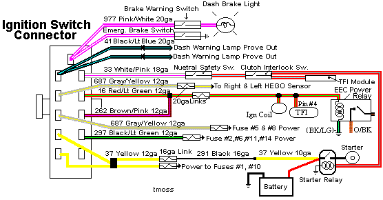
The ignition switch gets power from the two yellow wires that are supplied power by a fuse link located in the wiring harness that connects to the starter solenoid.
Diagram courtesy of Tmoss & Stang&2birds
I.) The coil is mounted on the driver’s side strut tower on most EFI Mustangs. It gets power from a red/green wire and a brown/pink wire from the ignition switch. That wire from the ignition switch feeds a 20 gauge blue fuse link that connects to the red/green wire. The fuse link protects the wiring and the ignition switch, since the fuse link for the two yellow power supply wires has a much higher current rating. Without the smaller fuse link protecting the smaller wiring used in the ignition circuit, a short there would cause the red/green wire to overheat and burn up.
II.) The TFI module is mounted on the side of the distributor and supplies the ground for the coil. Every automotive power supply circuit uses the ground as the return path to carry power back to the negative side of the battery. The TFI switches the tan/yellow wire coming from the coil to ground. It gets power from the red/green wire when the ignition switch is in the Run position.
The red/lt blue wire supplies a signal to turn on more power (dwell time) when the engine is cranking. The increased dwell can cause excessive current draw if the red/blue wire remains energized when the ignition switch is in the Run position. The trigger signal comes from the PIP sensor when cranking and the computer when the engine is running. The SPOUT jumper plug enables computer controlled spark advance. When the SPOUT is removed, spark advance is locked at the setting determined by the mechanical position of the distributor.
III.) The PIP sensor is in the bottom of the distributor under the shutter wheel. It is a Hall effect magnetic sensor that senses a change in the magnetic field when one of the slots in the shutter wheel uncovers the sensor. Then it supplies a pulse that triggers the TFI module to provide a ground to the ignition coil. A bad PIP will often set code 14 in the computer and cause hot start problems. Replacing the PIP sensor requires removal of the distributor and pressing the gear off the distributor shaft to expose the sensor. For most people, a remanufactured distributor ($55-$75) is the solution, since they may not have access to a press.
IV.)
Troubleshooting the ignition system – no spark or weak spark. All the tests are done with the ignition switch in the Run position unless specified otherwise. A safety pin may be used to probe the wiring connectors from the back side.
1.) Check for 12 volts at the yellow wires on the ignition switch. No 12 volts and the fuse link near the starter solenoid has open circuited.
2.) Check for 12 volts on the red/green and brown/pink wires coming out of the ignition switch. No 12 volts, replace the ignition switch.
3.) Check for 12 volts at the ignition coil. No 12 volts and the blue 20 gauge fuse link has open circuited.
4.) Check for 12 volts at the red/green wire on the TFI module. No 12 volts and you have wiring problems.
5.) Remove the small red/blue wire from the starter solenoid (looks like it is stuck on a screw). This is a safety measure to keep the engine from turning while you are making measurements. Have a helper turn the ignition switch to Start and look for 12 volts on the red/lt blue wire on the TFI module. No 12 volts and you will have starting problems, but push starting the car will work OK. No 12 volts, replace the ignition switch. Be sure to reconnect the red/blue wire to the starter when you finish.
6.) Check the red/blue wire to make sure that it has less than 8 volts when the ignition switch is in the Run position.
7.) A noid light available from any auto parts store, is one way to test the PIP pulse. The computer uses the PIP signal to trigger the fuel injectors. The noid light plugs into the fuel injector harness in place of any easily accessible injector. Plug it in and it will flash if the PIP is working. No flash from the noid light and the PIP is suspect. To confirm the PIP is being the source of the non flashing noid light, look for 12 volts on the red injector wiring. Good 12 volts and no flashing noid light means the PIP has failed.
8.) Remove the SPOUT plug from the harness and try to start the engine. If it starts, replace the PIP. This is a common no start condition when the engine is hot.
9.) The TFI module is a go/no go item when you have a no spark/weak spark condition on a cold engine. It either works or it doesn’t.
The TFI failure mode on a running car is usually a high speed miss on a warm engine. Many auto parts stores will test your TFI module for free. Bring along a hair dryer to get it hot while testing it and run several test cycles, since it often gets weak when it heats up.
Spraying the TFI module with “canned air” used to dust computer keyboards while the engine is hot and misfiring is one way to check the TFI. Turn the can upside down and spray away; this will cool the TFI of quickly. If it stops missing, the TFI is the likely suspect.
The coil is somewhat more difficult to pinpoint as a problem. A good coil will make a nice fat blue spark 3/8”-1/2” long. The problem is that one person’s perception of a fat blue spark looks like may not be accurate enough to spot a weak coil. The coil is cheap enough ($13-$16) that having a known good working spare might be a good idea.
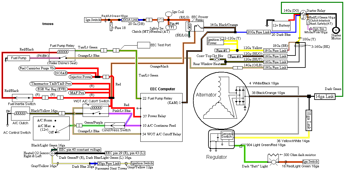
diagram courtesy of Tmoss & Stang&2Birds
See the following website for some help from Tmoss (diagram designer) & Stang&2Birds (website host) for help on 88-95 wiring
http://www.veryuseful.com/mustang/tech/engine/ Everyone should bookmark this site.
Ignition switch wiring
http://www.veryuseful.com/mustang/tech/engine/images/IgnitionSwitchWiring.gif
Fuel, alternator, A/C and ignition wiring
http://www.veryuseful.com/mustang/tech/engine/images/fuel-alt-links-ign-ac.gif
Complete computer, actuator & sensor wiring diagram for 88-91 Mass Air Mustangs
http://www.veryuseful.com/mustang/tech/engine/images/88-91_5.0_EEC_Wiring_Diagram.gif
Vacuum diagram 89-93 Mustangs
http://www.veryuseful.com/mustang/tech/engine/images/mustangFoxFordVacuumDiagram.jpg
HVAC vacuum diagram
http://www.veryuseful.com/mustang/tech/engine/images/Mustang_AC_heat_vacuum_controls.gif
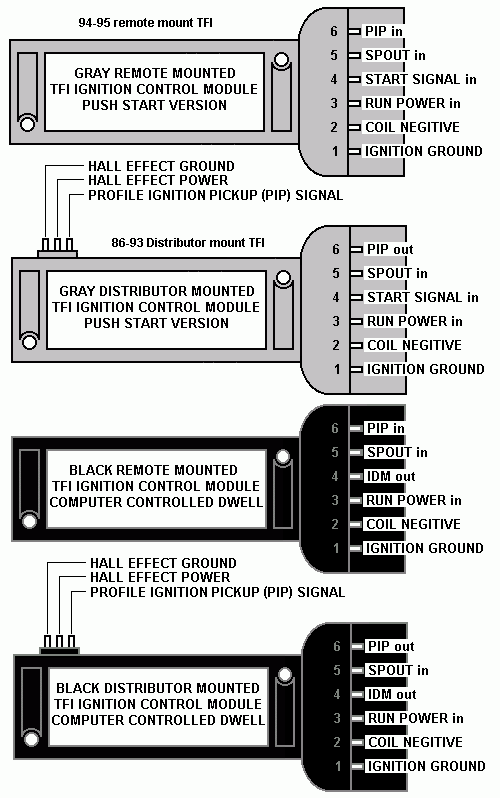
TFI module differences & pinout
http://www.veryuseful.com/mustang/tech/engine/images/TFI_5.0_comparison.gif


