Is It The Computer Or Is It Just Me?

timhodge

Founding Member
Aug 22, 2001
89
0
6
89 LX manual with a9l ecm died a couple weeks ago. No recent trouble prior. The fuel pump was off and on erratically with the key on engine off. So probably ecm trouble, right? I checked all the wiring related to the fuel pump, including the relay. Checked the power and ground to the ecm. All ok so I sent the ecm to be repaired. They replaced the three usual leaky capacitors and bench tested it ok. Reinstalled it. It ran for about ten minutes and started the same thing. Died, Turned key off and on. Fuel pump keeps running KOEO, wot throttle relay chattering, and some of the pollution system solenoids clicking on and off. I sent it back to the shop where they replaced the cpu and again said it tested ok. Reinstalled it, ran 10 minutes and shut off. Same thing with the fuel pump.
So before I go and try to find a good used ecm to throw at it, does anyone think it's NOT the ecm? Any ideas on what else to test and/or what to test before installing a new computer to make sure the same thing that destroyed this one doesn't destroy another one?
And the last I heard an a9l a3m or a9p are interchangeable on a manual, correct.
Thanks
 
You are hearing results of the power being turned off and on. That's why you hear the relays chattering.

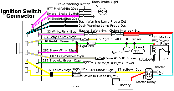
1.) Check the ignition switch
Recall on Ford Ignition switches:

Revised 7-June-2014 to add Torx bit picture and source. Also added replacement ignition switch wiring pigtail picture, part numbers and sources.

Some of the symptoms of ignition switch problems are things that don’t work or are intermittent like radio, turn signals, wipers or heater.

There was a FREE recall on Ford ignition switches. They overheat and sometimes catch fire. That burns up the steering column and sometimes the car interior. Since this is very old information, you may not be able to get the switch replaced for free anymore. The auto parts stores sell the switches for $13-$15.

4.webp


4.webp


4.webp


While you are working on the switch, check the wiring and connector closely. A replacement connector with new wiring pigtails is available from most auto parts stores

AutoZone and Advanced Auto Parts have the same Part Number: 434 - may have to order, not always in stock

Advanced Auto Parts alternate part number: PT5534

20974527_bwd_pt5534_pri_larg.webp


Saleen0679 was nice enough to dig this up for us awhile back: Replace a 1979-1993 Ignition Switch Assembly

Torx bit set from Advance Auto Parts

9021337_atc_ac571w1386_pri_larg.jpg


Autocraft torx bit set – have small hole in tip for tamper proof screws.
Part No. AC571/W1386 Cost approx. $12 +tax

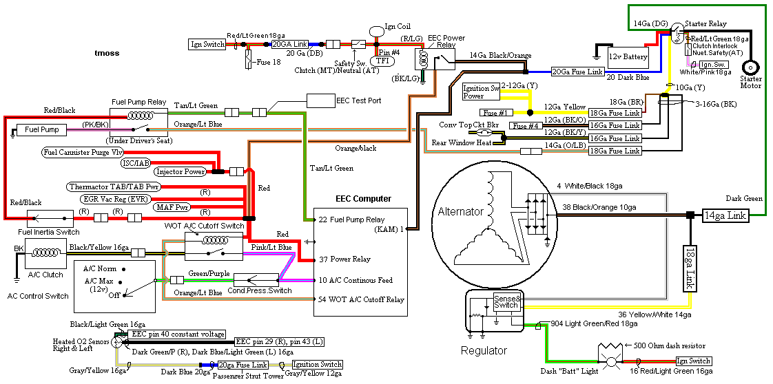
Diagrams courtesy of Tmoss & Stang&2birds

Ignition switch wiring
IgnitionSwitchWiring.gif


Fuel, alternator, A/C and ignition wiring
fuel-alt-links-ign-ac.gif


2.) Dump the codes - that is an always do, first step with any Mustang made after 1985. The computers are very reliable and seldom have problems; usually it is a relay, actuator, sensor or wiring that is the problem.

Dump codes sticky

Look at the top of the 5.0 Tech forum where the sticky threads are posted. One of them is how to dump the computer codes. Codes may be present even if the CEL(Check Engine Light) isn’t on. I highly suggest that you read it and follow the instructions to dump the codes. http://www.stangnet.com/mustang-forums/threads/how-to-pull-codes-from-eec4.889006/


See the following website for some help from Tmoss (diagram designer) & Stang&2Birds (website host) for help on 88-95 wiring http://www.veryuseful.com/mustang/tech/engine/ Everyone should bookmark this site.

Complete computer, actuator & sensor wiring diagram for 91-93 Mass Air Mustangs
http://www.veryuseful.com/mustang/tech/engine/images/91-93_5.0_EEC_Wiring_Diagram.gif

Complete computer, actuator & sensor wiring diagram for 88-91 Mass Air Mustangs
http://www.veryuseful.com/mustang/tech/engine/images/88-91_5.0_EEC_Wiring_Diagram.gif

Ignition switch wiring
http://www.veryuseful.com/mustang/tech/engine/images/IgnitionSwitchWiring.gif

Fuel, alternator, A/C and ignition wiring
http://www.veryuseful.com/mustang/tech/engine/images/fuel-alt-links-ign-ac.gif

O2 sensor wiring harness
http://www.veryuseful.com/mustang/tech/engine/images/mustangO2Harness.gif

Vacuum diagram 89-93 Mustangs
http://www.veryuseful.com/mustang/tech/engine/images/mustangFoxFordVacuumDiagram.jpg

HVAC vacuum diagram
http://www.veryuseful.com/mustang/tech/engine/images/Mustang_AC_heat_vacuum_controls.gif

TFI module differences & pin out
http://www.veryuseful.com/mustang/tech/engine/images/TFI_5.0_comparison.gif

Fuse box layout
http://www.veryuseful.com/mustang/tech/engine/images/MustangFuseBox.gif

87-92 power window wiring
http://www.veryuseful.com/mustang/tech/engine/images/mustang87-92 PowerWindowWiring.gif

93 power window wiring
http://www.veryuseful.com/mustang/tech/engine/images/mustang93PowerWindows.gif

Visual comparison of the Ford Fuel Injectors, picture by TMoss:
http://www.veryuseful.com/mustang/tech/engine/images/Ford_Injector_Guide.jpg
 
Thanks for the reply. I did the ign switch a couple years ago. I have monitored the power supply to the ecm during these events and it is staying constant. The ecm power relay is staying closed as it should and the kapwr never falters. Grounds are <1ohm.
Sorry. I should have mentioned I can't pull any codes. Just get zip. Well, actually I have a constant ground on the data out wire with the key on. If I put a meter between it and +12v I get 12v instead of the codes. Key off it goes away. If that helps.
Always appreciate hearing your thoughts.
 
Last edited:
Shouldn't that get 5v on the reference for pulling codes? I believe putting 12v on it burns the sigrtn trace.
I probably wasn't clear. The 12v reading is between the bat+ and the tan wire that also goes to the cel. I'm not connecting 12v to the sig return, the black/white. It gets jumpered to the sti connector. Actually I don't know what's on the sti connector. Maybe 5v? I'm going to check. Thanks for keeping me honest.
 
Computer will not go into diagnostic mode on 86-90 model 5.0 Mustangs

Disconnect the battery positive terminal before making any resistance checks.
The voltage drop in the ground cable will cause incorrect resistance readings.


How it is supposed to work:
The black/white wire (pin 46) is signal ground for the computer. It provides a dedicated ground for the EGR, Baro, ACT, ECT, & TPS sensors as well as the ground to put the computer into self test mode. If this ground is bad, none of the sensors mentioned will work properly. That will severely affect the car's performance. You will have hard starting, low power and drivability problems. Since it is a dedicated ground, it passes through the computer on its way to the computer main power ground that terminates at the battery pigtail ground. It should read less than 1.5 ohms when measured from anyplace on the engine harness with the battery pigtail ground as the other reference point for the ohmmeter probe.

What sometimes happens is that the test connector black/white wire gets jumpered to power which either burns up the wiring or burns the trace off the pc board inside the computer. That trace connects pins 46 to pins 40 & 60.

The STI (Self Test Input ) is jumpered to ground to put the computer into test mode. Jumpering it to power can produce unknown results, including damage to the computer. The ohm test simply verifies that there are no breaks in the wiring between the test connector and the computer input.

How to test the wiring :
With the power off, measure the resistance between the computer test ground (black/white wire) on the self test connector and battery ground. You should see less than 1.5 ohms.

attachment.php?attachmentid=58312&stc=1&d=1242744354.gif


If that check fails, remove the passenger side kick panel and disconnect the computer connector. There is a 10 MM bolt that holds it in place. Measure the resistance between the black/white wire and pin 46 on the computer wiring connector: it should be less than 1.5 ohms. More that 1.5 ohms is a wiring problem. If it reads 1.5 ohms or less, then the computer is suspect. On the computer, measure the resistance between pin 46 and pins 40 & 60: it should be less than 1.5 ohms. More that that and the computer’s internal ground has failed, and the computer needs to be repaired or replaced.

See http://www.stangnet.com/mustang-forums/749974-computer-issue.html#post7490537 for Joel5.0’s fix for the computer internal signal ground.

If the first ground check was good, there are other wires to check. Measure the resistance between the STI computer self test connector (red/white wire) and pin 48 on the computer main connector: it should be less than 1.5 ohms. More that 1.5 ohms is a wiring problem

The following is a view from the computer side of the computer wiring connector: it is for an A9L, A9P computer.
eec-iv-computer-connector-for-5-0-mustang-gif.88243.gif


a9x-series-computer-connector-wire-side-view-gif.71316.gif


Diagram courtesy of Tmoss & Stang&2birds

Check out the diagram and notice all the places the black/white wire goes. Almost every sensor on the engine except the MAF is connected to it.

88-91_5.0_EEC_Wiring_Diagram.gif


See the following website for some help from Tmoss (diagram designer) & Stang&2Birds
(website host) for help on 88-95 wiring http://www.veryuseful.com/mustang/tech/engine

See the graphic for the 10 pin connector circuit layout.
?temp_hash=3ef2497fff29a7a9daee955cf93e5805.webp