mustang II spindles

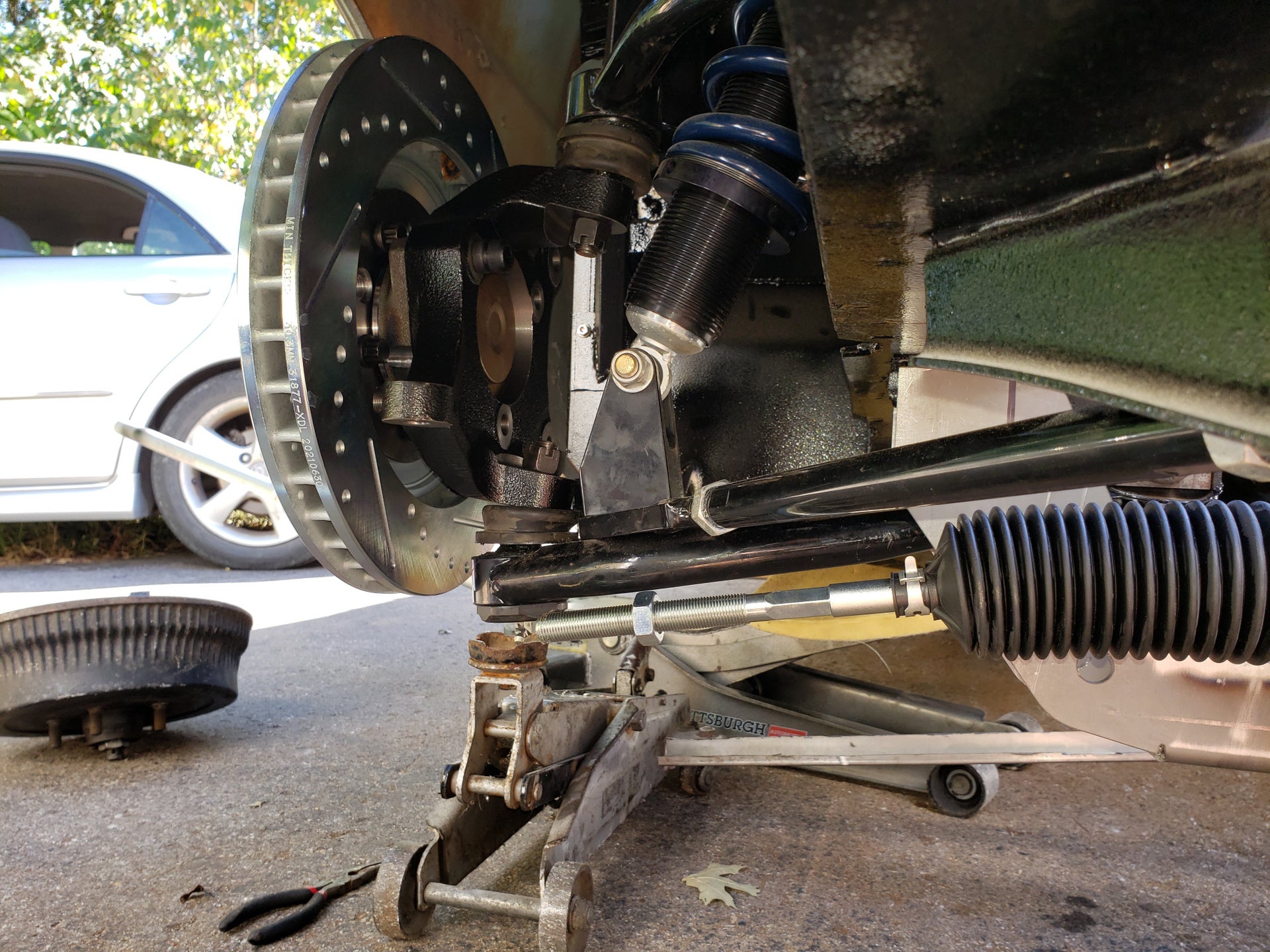
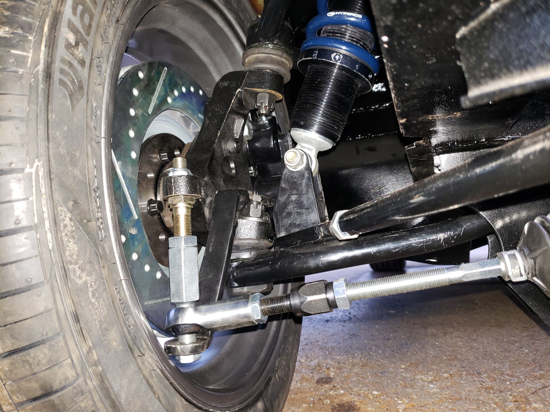
I'm not sure I understand the concern about needing a taller spring to clear the fender, but I had already rolled the fender lips to fit the 17x8" wheels. As you can see I'm using my own design control arms (very close to the RMP design) and the upper arms had to be taken in all the way to bring the tire comfortably inside the wheel well. I have my car lowered about 1 3/4".

The hub I'm using now is Wilwood part number 270-9320. It's designed to be used with a hat. The old Wilwood hub I was using stuck out further and also had to have a half inch spacer to make the wheel clear the upper ball joint.

The machine shop has told me for 3 weeks now that my caliper brackets would be ready next week. I'm starting to think he's just messing with me. I need to stop by tomorrow to see what's going on. Until everything is bolted together and I've actually swung it through the entire range of motion both up and down and lock to lock, I won't make any claims as to how well everything works. I had to have several parts re-machined because they didn't fit right. I paid for the re-work, so I don't think he has any reason to be upset with me, but I think that's when he lost his enthusiasm for my project.
 
  • Sponsors (?)


Well, the concern is just that the 2" drop spindle is more like 2.8" as compared with a stock vintage spindle. So if you want to keep the suspension in its geometric range,with say a 1" lowering spring, you'd end up nearly 4 inches lower.

Now my springs are of an unknown age, but four inches on my 65 puts the tire up near the accent crease. I'd have to make fenders unless I really pulled in my tires, which isn't what I'm going for.

Hope that machinist gets the work done. Sucks when you're waiting on someone else like that.
 
OK, I understand how the stock suspension would create a limitation. I'm using AFCO coilover shocks with a 7" stroke and 12" open springs. That's huge compared to a stock shock/spring arrangement. That allows plenty of room for adjustment.

I don't know how you came up with a 2.8" actual drop. It didn't take much adjustment of the spring to maintain the ride height I wanted, so I'd say 2.0" was pretty accurate.
 
I worked out the stock lbj to be about 1.22in. long when mounted, based on that at an 11 degree angle you go down 1.18in vertical. The wilwood spindle has its lbj mount at 2.3in. down from the spindle line. That gives you 3.48in. versus the measurement for the stock one which I have as 2.77in.

Then the 2" drop is at 5.48 vs. 2.77, which is a 2.71in. difference.
Keep in mind the second decimal place is not likely accurate in any but the wilwood measurements.

Helmantel made this and some other comparisons here:
http://www.stangnet.com/mustang-forums/7989062-post139.html

Now .7" isn't the end of the world, however from what I've read this geometry is actually in a better range 1" lower than stock, which puts it all a long ways down from factory. But admittedly, while my car seems tall it's difficult to tell how kind time has been to my springs, so it's kind of tough to tell where It'd actually be at 1" down from stock.
 
Interested in info on this subject

I am building a drag only 65 Mustang and would like info on using the Mustang II spindles for rear steer. Does anyone have any pictures or info on this ? The car will be drag only. I have some tubular uppers and am making tubular lowers. Will it be an issue mounting the calipers on the front side of the spindles and does that effect braking at all? I will probably be using Areospace brakes. The car will have a 25.5 chassis and will see times in the 8 second range at over 150 mph. Thanks for any info. Jim.
 
I am building a drag only 65 Mustang and would like info on using the Mustang II spindles for rear steer. Does anyone have any pictures or info on this ? The car will be drag only. I have some tubular uppers and am making tubular lowers. Will it be an issue mounting the calipers on the front side of the spindles and does that effect braking at all? I will probably be using Areospace brakes. The car will have a 25.5 chassis and will see times in the 8 second range at over 150 mph. Thanks for any info. Jim.

why do you want to run MII spindles? What advantages are you looking for? I think trying to make an MII spindle fit is not worth the trouble. The main thing will be the custom steering arms needed to obtain some reasonable ackermann.
 
why do you want to run MII spindles? What advantages are you looking for? I think trying to make an MII spindle fit is not worth the trouble. The main thing will be the custom steering arms needed to obtain some reasonable ackermann.

if he is building a drag only car, then the ackerman doesnt matter, and he can use lighter front brakes since he will likely be using front runner tires. most of the braking power will come from the rear.
 
if he is building a drag only car, then the ackerman doesnt matter, and he can use lighter front brakes since he will likely be using front runner tires. most of the braking power will come from the rear.
i understand that its a drag car. I am also building a 65 mustang drag car. Check out the thread another coilover by Bryce.

but light weight brakes are available for the stock spindles.


Posted via Mobile Device
 
Not only that, but I would guess the stock spindles to be lighter than the wilwood ones. And from the little I know about drag cars, I don't think dropping the front end is an advantage.
 
Time to dig this thread up from the graveyard I think. What I am doing is attempting to use aftermarket MII drop spindlesspindles on aftermarket early mustang control arms in a front steer application. This is what I have:

20221008_150501-1-jpg.863031


There are of course a number of issues I have to solve to make this work...but I need to start with basics. In this case the ball joints. Everything I read said they were essentially the same between the MI and the MII, and indeed, the taper itself does seem to be the same, but the diameter of the stud seems to be different. The stock spindle sat about 3/8" lower(and higher) on the ball joints than the MII spindle. The amusing thing is the spindle height difference between the 2 is 3/4" so regardless of which spindle is used, the RCA stays the same...at least using these ball joints. These are aftermarket Moog "problem solver" ball joints that screw in. I was hoping someone could point me to the part numbers I need for ones that will fit a bit better. The other big problem here is steering arm height...but that may well change since the crossmember I am using to hang the rack has not reached final fitment yet. I am hoping a bump-steer kit will be enough to take care of it.
Why not simply get one of the various Mustang II-based kits that are already out there to do this?

 
@wicked93gs I just saw your post here on this old thread. I have work in progress that includes installing M II spindles on a '65. So far the spindles are on and the'65 upper ball joint taper fits the M II. Also the lower does too. I'm at the point of finishing a front crossmember to hold the R&P that also replaes the tube crossmember that was under the early '65 engine. Also scoping out how to build an angled boxed in section in the part of the framerails near the firewall to use the early strut rods to brace the LCAs. There is an adjustable version available. I'm in north Alabama 2 hours south of you You have a PM.
 
Since this thread won't die, I have a few thoughts on the topic.

While Mustang II spindles are front steer, the first couple of years of the Pinto has rear steer and can be adapted easier.

Ackerman is important in road cars, and more important in road race cars. Otherwise they still wouldn't be using it. Carroll Smith has a lot of good info on Ackerman, here is just a bit:

Screenshot_20230913-151931_Drive.jpg

Screenshot_20230913-210319_Drive.jpg


Bump steer on our cars can be nearly eliminated if we get the control arms and steering arm aligned correctly. Here are a couple of ways to accomplish it, and they don't have to be parallel. The second pic is similar to Mustang suspension.

Screenshot_20230913-151758_Drive.jpg
Screenshot_20230913-151736_Drive.jpg
 
Oh yeah...I finished my MII spindle conversion...it works and Ackerman is fine is the long and the short of it. There are a few qualifications to actually make it work(such as a 4" shortened steering rack and 17"+ wheels are required) but it does work.
 
I have a whole thread on the conversion over on vintage mustang forums: https://www.vintage-mustang.com/thr...fferent-kind-of-hybrid.1206452/#post-10712472

20230101_163914-1-jpg.874292


I did have to build "supplemental" steering arms because I had to drop the rod end attachment point so far to maintain the correct bump-steer(also why 17"+ wheels are needed). Al alternative to that though is to use a Willwood MII spindle with the bolt-on steering arms instead...then you could fabricate a steering arm low enough to get away with just one. Though this design does have some nice features you couldn't get with a single steering arm. The supplemental steering arm is strictly to prevent the bump-steer "stud" from flexing under heavy cornering(maybe its better to call it a stabilizing arm)...I would not trust it as the only steering arm.