See the graphic for the 10 pin connector circuit layout.
Computer wiring harness connector, wire side
Computer wiring harness connector, computer side
Fuel injector wiring harness sensors for a 5.0 mustang
Code 15 or 511 - No Keep Alive Memory power to PCM pin 1 or bad PCM (Memory Test Failure).
Revised 4-Jan-2019 to add removing any custom tuning chip for minimum configuration testing.
The voltage to the Keep Alive Memory (KAM) is missing (wiring problem) or the KAM is bad. The KAM holds all of the settings that the computer "learns" as it operates and all the stored error codes that are generated as a result of something malfunctioning while the engine is running. Use a voltmeter to check the voltage to the pin 1 on the computer - you should always have 12 volts. No constant 12 volts = bad wiring. If you do always have the 12 volts, then the KAM may be bad and the computer is faulty. Read on further to make this determination, since there are some exceptions.
Clearing the codes by pressing a button on the scan tool or disconnecting the test jumper used to start the code dump does not erase the “learned settings”. Disconnecting the computer from the wiring harness or disconnecting the battery (either power or ground cable) will erase the “learned settings” If the computer has to "relearn" all the optimum settings every time it powers up, the initial 15-30 minutes of operation may exhibit surges, poor low speed performance, and rough idle.
Note that some aftermarket chips will cause code 15 to set. Disconnect the battery and remove the chip, reconnect the battery and retest. If you have a custom burned chip using the data gathered from a dyno session, this may not be advisable since it may drastically alter the fuel/air and timing tables.
Disconnect the battery negative terminal for the next step.
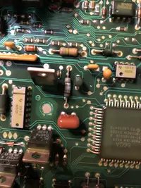
Remove the passenger side kick panel and examine the computer. It is held in place by a diagonal plastic strap and 2 screws in the strap. The end of the computer opposite the wiring harness may have an accessory PC board with a big chip in a socket. That chip is a custom tune to accommodate the mods that affect fuel /air mixture, ignition timing and emissions equipment. If it is present, remove it and see if the engine runs any better. Remember that the car will need to be driven at highway speeds for at least 15-20 minutes in order for the computer to relearn the adaptive settings.
For stock engines or engines with minor modifications (OEM cylinder heads, stock 19 LB injectors, no NO2 or pressurized induction).
Before replacing the computer, remove the battery ground cable for about 20 minutes. This will clear all the codes and “learned settings”. Retest after several days of running. If the 15 code is gone, then don't worry about it. If it is still there, then you get to do some troubleshooting.
See the following website for some help from Tmoss (diagram designer) & Stang&2
Birds (website host) for help on 88-95 wiring
http://www.veryuseful.com/mustang/tech/engine/
Diagram courtesy of Tmoss & Stang&2birds
http://www.veryuseful.com/mustang/tech/engine/images/IgnitionSwitchWiring.gif
http://www.veryuseful.com/mustang/tech/engine/images/fuel-alt-links-ign-ac.gif
http://www.veryuseful.com/mustang/tech/engine/images/88-91_5.0_EEC_Wiring_Diagram.gif
Code 24 - Intake Air Temperature (ACT) sensor out of range.
Bad sensor, bad wiring. The ACT for Mustangs built before 95 is in the
#5 intake runner. It measures the air temperature in the intake to help
computer the proper air/fuel ratio.
Note that that if the outside air temp is below 50 degrees F that the test for the ACT can be in error. Warm the engine up to operating temperature and retest.
ACT & ECT test data:
The ACT & ECT have the same thermistor, so the table values are the same
Pin 7 on the computer - ECT signal in. at 176 degrees F it should be .80 volts
Pin 25 on the computer - ACT signal in. at 50 degrees F it should be 3.5 volts.
It is a good number if the ACT is mounted in the inlet airbox. If it is mounted in
the lower intake manifold, the voltage readings will be lower because of the heat transfer.
Here's the table :
50 degrees F = 3.52 v
68 degrees F = 3.02 v
86 degrees F = 2.62 v
104 degrees F = 2.16 v
122 degrees F = 1.72 v
140 degrees F = 1.35 v
158 degrees F = 1.04 v
176 degrees F = .80 v
194 degrees F = .61
212 degrees F = .47 v
230 degrees F = .36 v
248 degrees F = .28 v
Ohms measures at the computer with the computer disconnected,
or at the sensor with the sensor disconnected.
50 degrees F = 58.75 K ohms
68 degrees F = 37.30 K ohms
86 degrees F = 27.27 K ohms
104 degrees F = 16.15 K ohms
122 degrees F = 10.97 K ohms
140 degrees F = 7.60 K ohms
158 degrees F = 5.37 K ohms
176 degrees F = 3.84 K ohms
194 degrees F = 2.80 K ohms
212 degrees F = 2.07 K ohms
230 degrees F = 1.55 K ohms
248 degrees F = 1.18 k ohms
Code 67
Revised 18-Mar-2017 to include warning about the necessity of having a 5 speed O2 Sensor wiring harness when bypassing the wiring for test purposes
Cause of problem:
Clutch not depressed (5 speed) or car not in neutral (5 speed and auto) or not in park (auto) or A/C in On position when codes where dumped. Possible neutral safety switch or wiring problem. This code will prevent you from running the Key On Engine Running tests.
External evidence from other sources claims that a code 67 can cause an idle surge condition. Do try to find and fix any issues with the switch and wiring if you get a code 67.
What the NSS (Neutral Safety Switch) does:
5 speed transmission: It has no connection with the starter, and the engine can be cranked without it being connected.
Auto transmission: It is the safety interlock that prevents the starter from cranking the engine with the transmission in gear.
What it does for both 5 speed and auto transmission cars:
The computer wants to make sure the A/C is off due to the added load on the engine for the engine running computer diagnostic tests. It also checks to see that the transmission is in Neutral (5 speed and auto transmission) and the clutch depressed (T5, T56, Tremec 3550 & TKO)). This prevents the diagnostics from being run when the car is driven. Key On Engine Running test mode takes the throttle control away from the driver for several tests.
This could prove hazardous if the computer was jumpered into test mode and then driven.
The following is for 5 speed cars only. Do not do this unless you are sure that you have a 5 speed O2 Sensor harness!!!! Smoke, sparks and expensive pain in the wallet may ensue if you don’t.
The NSS code 67 can be bypassed for testing. You will need to temporarily ground computer pin 30 to the chassis. Computer pin 30 uses a Lt blue/yellow wire. Remove the passenger side kick panel and then remove the plastic cover from the computer wiring connector. Use a safety pin to probe the connector from the rear. Jumper the safety pin to the ground near the computer.
Be sure to remove the jumper BEFORE attempting to drive the car!!!
Code 85 CANP solenoid - The Carbon Canister solenoid is inoperative or missing.
Revised 11 –Jan_2015 to add warning about vacuum leaks due to deteriorated hose or missing caps on vacuum lines when the solenoid is removed.
Check vacuum lines for leaks and cracks. Check electrical wiring for loose connections, damaged wiring and insulation. Check solenoid valve operation by grounding the gray/yellow wire to the solenoid and blowing through it.
The computer provides the ground for the solenoid. The red wire to the solenoid is always energized any time the ignition switch is in the run position.
If you disconnected the carbon canister and failed to properly cap the vacuum line coming from under the upper intake manifold, you will have problems. You will also have problems if the remaining hose coming from under the upper intake manifold or caps for the vacuum line are sucking air.
Charcoal canister plumbing - one 3/8" tube from the bottom of the upper manifold to the rubber hose. Rubber hose connects to one side of the canister solenoid valve. Other side of the solenoid valve connects to one side of the canister. The other side of the canister connects to a rubber hose that connects to a line that goes all the way back to the gas tank. There is an electrical connector coming from the passenger side injector harness near #1 injector that plugs into the canister solenoid valve. It's purpose is to vent the gas tank. The solenoid valve opens at cruse to provide some extra fuel. The canister is normally mounted on the passenger side frame rail near the smog pump pulley.
Connecting the gas tank vent line directly to the intake manifold will result in fuel vapor being constantly sucked into the intake manifold. There is unmetered fuel that the computer cannot adjust for. The result is poor idle and poor fuel economy.
It does not weigh but a pound or so and helps richen up the cruse mixture. It draws no HP & keeps the car from smelling like gasoline in a closed garage. So with all these good things and no bad ones, why not hook it up & use it?
The purge valve solenoid connector is a dangling wire that is near the ECT sensor and oil filler on the passenger side rocker cover. The actual solenoid valve is down next to the carbon canister. There is about 12"-16" of wire that runs parallel to the canister vent hose that comes off the bottom side of the upper intake manifold. That hose connects one port of the solenoid valve; the other port connects to the carbon canister.
The purge valve solenoid should be available at your local auto parts store.
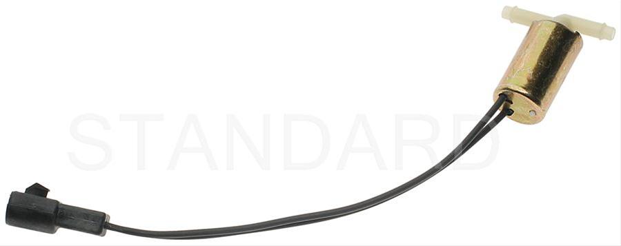
Purge valve solenoid:
The carbon canister is normally mounted on the passenger side frame rail near the smog pump pulley.
Carbon Canister:
Code 87 – fuel pump primary circuit failure. The fuel pump lost power while the engine was running. Check fuel pump relay, check inertia switch, wiring to/from inertia switch, red wire going to inertia switch for +12volts. Check the other side of inertia switch for +12 volts.
Diagram of the fuel pump wiring for 86-90 cars
Diagram of the fuel pump wiring for 91-93 cars.