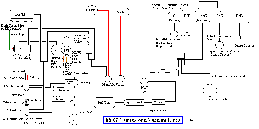
Some basic theory to clarify how things work is in order…
The EGR shuts off at Wide Open Throttle (WOT), so it has minimal effect on performance. The addition of exhaust gas drops combustion temperature, increases gas mileage and reduces the tendency of the engine to ping. It can also reduce HC emissions by reducing fuel consumption. The primary result of EGR usage is a reduction in NOx emissions.
The EGR system has a vacuum source (line from the intake manifold) that goes to the EVR, computer operated electronic vacuum regulator. The EVR is located on the back of the passenger side shock strut tower. The computer uses RPM, Load. and some other factors to tell the EVR to pass vacuum to open the EGR valve. The EGR valve and the passages in the heads and intake manifold route exhaust gas to the EGR spacer (throttle body spacer). The EGR sensor tells the computer how far the EGR valve is open. Then computer adjusts the signal sent to the EVR to hold, increase or decrease the vacuum. The computer adds spark advance to compensate for the recirculated gases and the slower rate they burn at.
Troubleshooting:
There should be no vacuum at the EGR valve when at idle. If there is, the EVR (electronic vacuum regulator) mounted on the backside of the passenger side wheelwell is suspect. Check the vacuum line plumbing to make sure the previous owner didn’t cross the vacuum lines.
Diagram courtesy of Tmoss & Stang&2birds. (the diagram says 88 GT, but the EGR part is the same for 86-93 Mustangs)
The EGR sensor is basically a variable resistor, like the volume control on a radio. One end is 5 volt VREF power from the computer (red/orange wire). One end is computer signal ground (black/white), and the middle wire (brown/lt green) is the signal output from the EGR sensor. It is designed to always have some small voltage output from it anytime the ignition switch is the Run position. That way the computer knows the sensor & the wiring is OK. No voltage on computer pin 27 (brown/lt green wire) and the computer thinks the sensor is bad or the wire is broken and sets code 31. The voltage output can range from approximately .6-.85 volt.
EGR test procedure courtesy of cjones
to check the EGR valve:
bring the engine to normal temp.
connect a vacuum pump to the EGR Valve
apply 5in vacuum to the valve.
if engine stumbled or died then EGR Valve and passage(there is a passageway through the heads and intake) are good.
if engine did NOT stumble or die then either the EGR Valve is bad and/or the passage is blocked.
if engine stumbled, connect vacuum gauge to the hose coming off of the EGR Valve
snap throttle to 2500 RPM (remember snap the throttle don't hold it there).
did the vacuum gauge show about 2-5 in vacuum?
if not, check for manifold vacuum at the EGR vacuum valve.
if you have manifold vacuum then connect vacuum gauge to the EGR valve side of the vacuum valve and snap throttle to 2500 RPM.
should read about 2-5 in vacuum
Late Model Restoration has the Ford Racing M-12071-N302 kit with the EGR valve & sensor along with the ACT & ECT sensors for $45. See
http://www.latemodelrestoration.com/iwwida.pvx?;item?item_no=M12071N302 1&comp=LRS for more details
I really don't recommend removing the cats since you are breaking several Federal laws that have stiff fines and jail penalties. Since you have already done so, here is the fix for the codes that you are going to set in the computer.
TAB & TAD solenoid valve eliminators – eliminate codes 81 & 82 and 44 & 94
Don’t do this if you have a catalytic converter H pipe. The catalytic converters must have the air from the smog pump or they will clog up and choke.
See
www.Newark.com for the resistors to replace the TAB & TAD solenoids
http://www.newark.com/jsp/Passives/Wirewound/OHMITE/43F82RE/displayProduct.jsp?sku=64K8974
If the link fails do a search using the park number
82 ohm, 3 watt wirewound resistor, 94 cents each.
Newark P/N 64K8974
Ohmite part # 43F82RE.
Pay a visit to your local Radio Shack to get some heat shrink and some crimp on tap terminals. They do not stock the resistors. Or you can use the Ford connector pin kit from AutoZone.
18 gauge crimp on taps Catalog #: 64-3053
Put the resistor inside the heat shrink tubing and crimp the connectors on. I would choose the Ford pin connectors since they should plug in the TAD wiring. That way you haven't modified the wiring so it is easy to re-install the TAD solenoids if emissions testing comes to your area.
Two flat pin connectors.
One 82 ohm, 3 watt resistor.
One piece 3/8" heat sink tubing 2" long.
Two pieces 3/16" heat shrink tubing 1 1/2" long.
Solder the pins onto the resistor leads using electrical solder.
Slide the 3/8" heat shrink tubing over the resistor.
Slide the two pieces of 3/16" heat shrink tubing over the two wires, leaving the flat part of the pins uncovered.
It helps to have the resistor leads straight and not bent as shown in the first picture when you apply heat to the heat shrink tubing. That way, the tubing shrinks more evenly.
Finally, apply heat to shrink all the tubing uniformly.
Bend the leads to fit the spacing on the female TAB & TAD connector sockets.
Push the connector pins of the completed resistor assembly into the empty female TAD or TAD connector sockets on the wiring harness. The resistor assemblies replace the missing solenoids: one resistor assembly per solenoid socket.
Do not crimp on the pins and wrap the mess with electrical tape and say you got the idea from me. If you do, and I hear of it, I will say unkind things about your intelligence and family heritage. Do Quality Work!
This information is for informational purposes only and is intended for use only on off road vehicles. It should not be used on any vehicle operated on public roads.
Operating a vehicle modified in such a manner on public roads is a violation of the EPA codes regarding modification of emission controlled vehicles.