Suspension Update

dolfan87

Founding Member
Dec 28, 2000
1,242
0
0
Lake Havasu, AZ
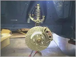
Hey I just wanted to give you guys/gals an update on my suspension. I got everything back from the powder coaters, and it turned out really nice.

There is a big off-road race this weekend, and the shop has been going like crazy to get ready for it. We are planning on making a big push for the 65-66 design starting next week, and we should have the 68-70 kits jigged up soon.

Anyway, here are a few snap shots I took with my phone. Sorry that the pic quality isn't the greatest, but my digital camera was out of juice.

Let me know what you guys think

Gram
 

Attachments

  • Finished Sus 1.webp
    Finished Sus 1.webp
    41 KB · Views: 1,076
  • Finished Sus 2.webp
    Finished Sus 2.webp
    32.2 KB · Views: 828
Very nice, I like the way you built the upper shock mount into the pivot shaft. And I also like how the strut rod mounting point is integrated into the lower shock mount. I think you guys are really on to something here.
 
It looks great! :nice: I do have a question though... and I can't remember if this came up in the previous thread... but what are the possibilities of engineering it to accept late model spindles? Would steering angles be severely effected? The reason I ask is that '03-'04 Mach and Cobra 13" brakes come up for sale rather frequently for $400 or less complete. My though is that if someone wanted your kit, and wanted big brakes, and late model spindles were an option, that would make the big brake swap much less expensive, thus making your kit even more attractive... (hint, hint). Just a thought. :shrug:

Keep up the good work! :flag:
 
DarkBuddha said:
It looks great! :nice: I do have a question though... and I can't remember if this came up in the previous thread... but what are the possibilities of engineering it to accept late model spindles? Would steering angles be severely effected? The reason I ask is that '03-'04 Mach and Cobra 13" brakes come up for sale rather frequently for $400 or less complete. My though is that if someone wanted your kit, and wanted big brakes, and late model spindles were an option, that would make the big brake swap much less expensive, thus making your kit even more attractive... (hint, hint). Just a thought. :shrug:

Keep up the good work! :flag:


Nice thought, but the new Mustangs are front steer. I am afraid it just isn't possible.

TT670 said:
Very nice, I like the way you built the upper shock mount into the pivot shaft. And I also like how the strut rod mounting point is integrated into the lower shock mount. I think you guys are really on to something here.

Actually, the lower shock mount only bolts through the strut rod plate. However the set up is very clean, and easy to install.

DukeGnarley said:
that setup could allow for some serious shock tower notching.

Oh how I wish that were true! Both the upper control arm shaft, and the upper shock mount bolt directly to the shock tower.

-------------

Thanks for the comments guys, I am hoping to have the car off the lift by tomorrow afternoon.


Gram
 
I have something to add, just trying to help the design.

The upper ball-joint connection looks weak to me, perhaps if the tubes came further out, that is, further around the front and back of the ball-joint, and you had a tube welding the two tubes together, behind the ball-joint plate, it would be stronger.

I think I'll do a little design, post pic later for ya.

EDIT: Here's the pic:

attachment.php


EDIT 2: Ok I just realised the UCA isn't stressed like the original setup, so maybe my idea is overkill.
 

Attachments

  • UCA.webp
    UCA.webp
    9.1 KB · Views: 534
Curious

Hi,
I notice that you have chosen a 0 degree incline on the upper ball joint relative to the arm. Stock is around 22 degrees and TCP run about 8 degrees. Are there other geometry changes that you have made to the system or mounting points that dictated 0?
jer
 
jmagilto said:
Hi,
I notice that you have chosen a 0 degree incline on the upper ball joint relative to the arm. Stock is around 22 degrees and TCP run about 8 degrees. Are there other geometry changes that you have made to the system or mounting points that dictated 0?
jer

That picture is misleading, there is actually 7 degrees on that arm, it just looks flat from the angle of my camera phone. We are going to test the system with it like this, and then see how it performs.

We shortened the arm, but left the stock attachment points. The curve so far looks great, but real world testing will prove if we built it correctly.

route666 said:
Ok I just realised the UCA isn't stressed like the original setup, so maybe my idea is overkill.

That 1/4" plate is swallowed a good two inches on both sides by the tube. You are correct that it is not stressed like a stock set-up.

We may look into doing more for the non coil over arms. Great pic by the way!

Gram
 
mdjay said:
Looks like quality stuff... I didn't realize you were so close to us.

What's production time looking like?

Call me next week if you can...

Jay


Production time will be a few weeks to a month and a half out. We have lined up testing for the kits, and as soon as we get everything fully tuned, then we will be set to go.

I will give you a shout.

Gram