Throwing Codes And Misfiring

87dixiegt

New Member
Aug 19, 2016
19
1
1
hey guys! New to the site here.

I recently bought an 87 gt and after a short time of owning it it started misfiring and some days not starting at all. It seems to misfire at about 3-4K rpm and if you are going full throttle (if you go half throttle it's fine) and I would like to get this fixed very soon but don't know where to start.

I ran the codes and it read 31, 85, and 95 anyone have some advice for me? Also the car was switched to MAF if that makes a difference? I can post pictures of the engine bay and or anything else that would be helpful if needed. Thanks!
 
  • Sponsors (?)


Did you get the engine running codes?

CODE: 31 (KOEO) - EVP circuit below minimum voltage. Vref (5 volt reference voltage supplied by the computer) missing or broken wire or bad connection in circuit. Use a DVM to check for 5 volts on the orange/white wire. If it is missing, look for +5 volts at the orange/white wire on the TPS or MAP sensor located on the firewall near the center of the car. Use the black/white wire for the ground for the DVM.
With the sensor removed from the EGR and still connected, press the plunger and watch the voltage change on the brown/lt green wire. Pull the passenger side kick panel and measure the voltage at the computer. You will need to remove the plastic cover over the wires and probe them from the backside. A safety pin may prove very useful for this task. Use pin 27, EVR input (brown/lt green wire) and pin 46, signal ground (black/white wire) to measure the voltage. The orange/white wire is Vref and should always be 5 volts -/+ .25 volt. Be sure to measure Vref at the EGR sensor to rule out any broken wires or bad connections.
Measuring the voltage at the computer helps you spot broken wiring and intermittent connections.
See the graphic for the 10 pin connector circuit layout.
?temp_hash=3ef2497fff29a7a9daee955cf93e5805.jpg


a9x-series-computer-connector-wire-side-view-gif.71316.gif


attachment.php?attachmentid=49009&d=1171639646.gif


Code 85 CANP solenoid - The Carbon Canister solenoid is inoperative or missing.

Revised 11 –Jan_2015 to add warning about vacuum leaks due to deteriorated hose or missing caps on vacuum lines when the solenoid is removed.

Check vacuum lines for leaks and cracks. Check electrical wiring for loose connections, damaged wiring and insulation. Check solenoid valve operation by grounding the gray/yellow wire to the solenoid and blowing through it.
The computer provides the ground for the solenoid. The red wire to the solenoid is always energized any time the ignition switch is in the run position.

If you disconnected the carbon canister and failed to properly cap the vacuum line coming from under the upper intake manifold, you will have problems. You will also have problems if the remaining hose coming from under the upper intake manifold or caps for the vacuum line are sucking air.

Charcoal canister plumbing - one 3/8" tube from the bottom of the upper manifold to the rubber hose. Rubber hose connects to one side of the canister solenoid valve. Other side of the solenoid valve connects to one side of the canister. The other side of the canister connects to a rubber hose that connects to a line that goes all the way back to the gas tank. There is an electrical connector coming from the passenger side injector harness near #1 injector that plugs into the canister solenoid valve. It's purpose is to vent the gas tank. The solenoid valve opens at cruse to provide some extra fuel. The canister is normally mounted on the passenger side frame rail near the smog pump pulley.

attachment.php?attachmentid=58191&stc=1&d=1241921055.gif


It does not weigh but a pound or so and helps richen up the cruse mixture. It draws no HP & keeps the car from smelling like gasoline in a closed garage. So with all these good things and no bad ones, why not hook it up & use it?


The purge valve solenoid connector is a dangling wire that is near the ECT sensor and oil filler on the passenger side rocker cover. The actual solenoid valve is down next to the carbon canister. There is about 12"-16" of wire that runs parallel to the canister vent hose that comes off the bottom side of the upper intake manifold. That hose connects one port of the solenoid valve; the other port connects to the carbon canister.

The purge valve solenoid should be available at your local auto parts store.

Purge valve solenoid:
6.jpg


The carbon canister is normally mounted on the passenger side frame rail near the smog pump pulley.
Carbon Canister:
CP2000photo%20primary__ra_p.jpg


The code 95 is most likely because the PO didn't run the extra wire for the fuel pump OK sense to the computer.

Code 95 Key On, Engine not Running - the following test path is for 86-90 model Mustangs.

The 95 code is because at one time or another, the fuel pump relay hiccupped and didn't provide power the pump when the computer told it to run. Sometimes this is a one time thing, other times it is a no run or runs poorly condition.

fuel-pump-wiring-89-90-5-0-mustang-jpg.55493.jpg


Using the diagram, check the red/black wire from the fuel pump relay: you should see 12 volts or so. If not, check the inertia switch: on a hatch it is on the driver’s side by the taillight. Look for a black rubber plug that pops out: if you don't find it, then loosen up the plastic trim. Check for voltage on both sides of the switch. If there is voltage on both sides, then check the Pink/black wire on the fuel pump relay: it is the power feed to the fuel pump. No voltage there, check the Orange/Lt blue wire, it is the power feed to the fuel pump relay & has a fuse link in it. If there is good voltage there & at the Pink/black wire, swap the relay.

Some Mass Air conversions neglect to run the extra fuel pump wire, and they always have a 95 code. See http://www.stangnet.com/tech/maf/massairconversion.html for more information on the Mass Air wiring conversion.

See the following website for some help from Tmoss (diagram designer) & Stang&2Birds (website host) for help on 88-95 wiring http://www.veryuseful.com/mustang/tech/engine/ Everyone should bookmark this site.

Ignition switch wiring
http://www.veryuseful.com/mustang/tech/engine/images/IgnitionSwitchWiring.gif

Fuel, alternator, A/C and ignition wiring
http://www.veryuseful.com/mustang/tech/engine/images/fuel-alt-links-ign-ac.gif

Complete computer, actuator & sensor wiring diagram for 88-91 Mass Air Mustangs
http://www.veryuseful.com/mustang/tech/engine/images/88-91_5.0_EEC_Wiring_Diagram.gif

Complete computer, actuator & sensor wiring diagram for 91-93 Mass Air Mustangs
http://www.veryuseful.com/mustang/tech/engine/images/91-93_5.0_EEC_Wiring_Diagram.gif

Vacuum diagram 89-93 Mustangs
http://www.veryuseful.com/mustang/tech/engine/images/mustangFoxFordVacuumDiagram.jpg

HVAC vacuum diagram
http://www.veryuseful.com/mustang/tech/engine/images/Mustang_AC_heat_vacuum_controls.gif

TFI module differences & pinout
http://www.veryuseful.com/mustang/tech/engine/images/TFI_5.0_comparison.gif

Fuse box layout
http://www.veryuseful.com/mustang/tech/engine/images/MustangFuseBox.gif


At this point none of the codes you supplied would cause the problem you described.

Does the problem occur only when the engine is warm and you are above half throttle?
 
  • Like
Reactions: 1 user
Wow thanks for that! Knew this forum would be a ton of help!

Yes the problem only occurs when you're above 2,500 rpm and above 75% throttle but it doesn't matter if it's warm or cold it still does it. It doesn't smell rich at all and the fuel systems is brand new (according to the previous owner) Sometimes the car won't start and sometimes it starts up just fine. Ignition issue maybe?

Where should I go from here? What would you suggest to do? I'll have to go home to confirm this but I think the egr and canister were both deleted.
 
Get the engine running codes and post them.

I have some suspicions that this may be ignition related, but I need the engine running codes to make a diagnosis.
 
Get the engine running codes and post them.

I have some suspicions that this may be ignition related, but I need the engine running codes to make a diagnosis.

I took your advice and just ran the codes.

with the engine off but ignition on the codes were 31, 85, and 95

with the engine on the codes were 94, 44, and 31

i checked 3 times to make sure i got it right.

what now? thanks
 
That is useful in that it does not point to fuel problems . That takes us back to the ignition system. I would suspect that the TFI module is the most likely source of your problem, followed by the PIP sensor in the distributor.

The no start condition may actually turn out to be helpful in narrowing down the choice of TFI or PIP sensor.

How the TFI ignition works in 86-93 model Mustangs:

Tools needed: DVM, noid light, safety pin.

Theory of operation:
The TFI ignition in 86-93 Mustangs has 4 main components: the ignition switch, the coil, the TFI module and the PIP sensor inside the distributor.

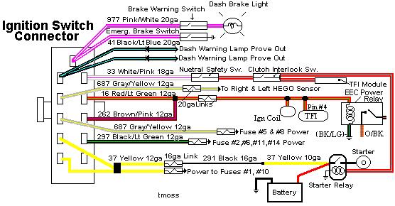
The ignition switch gets power from the two yellow wires that are supplied power by a fuse link located in the wiring harness that connects to the starter solenoid.

Diagram courtesy of Tmoss & Stang&2birds
IgnitionSwitchWiring.gif


I.) The coil is mounted on the driver’s side strut tower on most EFI Mustangs. It gets power from a red/green wire and a brown/pink wire from the ignition switch. That wire from the ignition switch feeds a 20 gauge blue fuse link that connects to the red/green wire. The fuse link protects the wiring and the ignition switch, since the fuse link for the two yellow power supply wires has a much higher current rating. Without the smaller fuse link protecting the smaller wiring used in the ignition circuit, a short there would cause the red/green wire to overheat and burn up.

II.) The TFI module is mounted on the side of the distributor and supplies the ground for the coil. Every automotive power supply circuit uses the ground as the return path to carry power back to the negative side of the battery. The TFI switches the tan/yellow wire coming from the coil to ground. It gets power from the red/green wire when the ignition switch is in the Run position. The red/lt blue wire supplies a signal to turn on more power (dwell time) when the engine is cranking. The increased dwell can cause excessive current draw if the red/blue wire remains energized when the ignition switch is in the Run position. The trigger signal comes from the PIP sensor when cranking and the computer when the engine is running. The SPOUT jumper plug enables computer controlled spark advance. When the SPOUT is removed, spark advance is locked at the setting determined by the mechanical position of the distributor.

III.) The PIP sensor is in the bottom of the distributor under the shutter wheel. It is a Hall effect magnetic sensor that senses a change in the magnetic field when one of the slots in the shutter wheel uncovers the sensor. Then it supplies a pulse that triggers the TFI module to provide a ground to the ignition coil. A bad PIP will often set code 14 in the computer and cause hot start problems. Replacing the PIP sensor requires removal of the distributor and pressing the gear off the distributor shaft to expose the sensor. For most people, a remanufactured distributor ($55-$75) is the solution, since they may not have access to a press.

IV.) Troubleshooting the ignition system – no spark or weak spark. All the tests are done with the ignition switch in the Run position unless specified otherwise. A safety pin may be used to probe the wiring connectors from the back side.
1.) Check for 12 volts at the yellow wires on the ignition switch. No 12 volts and the fuse link near the starter solenoid has open circuited.
2.) Check for 12 volts on the red/green and brown/pink wires coming out of the ignition switch. No 12 volts, replace the ignition switch.
3.) Check for 12 volts at the ignition coil. No 12 volts and the blue 20 gauge fuse link has open circuited.
4.) Check for 12 volts at the red/green wire on the TFI module. No 12 volts and you have wiring problems.
5.) Remove the small red/blue wire from the starter solenoid (looks like it is stuck on a screw). This is a safety measure to keep the engine from turning while you are making measurements. Have a helper turn the ignition switch to Start and look for 12 volts on the red/lt blue wire on the TFI module. No 12 volts and you will have starting problems, but push starting the car will work OK. No 12 volts, replace the ignition switch. Be sure to reconnect the red/blue wire to the starter when you finish.
6.) Check the red/blue wire to make sure that it has less than 8 volts when the ignition switch is in the Run position.
7.) A noid light available from any auto parts store, is one way to test the PIP pulse. The computer uses the PIP signal to trigger the fuel injectors. The noid light plugs into the fuel injector harness in place of any easily accessible injector. Plug it in and it will flash if the PIP is working. No flash from the noid light and the PIP is suspect. To confirm the PIP is being the source of the non flashing noid light, look for 12 volts on the red injector wiring. Good 12 volts and no flashing noid light means the PIP has failed.
8.) Remove the SPOUT plug from the harness and try to start the engine. If it starts, replace the PIP. This is a common no start condition when the engine is hot.
9.) The TFI module is a go/no go item when you have a no spark/weak spark condition on a cold engine. It either works or it doesn’t.
The TFI failure mode on a running car is usually a high speed miss on a warm engine. Many auto parts stores will test your TFI module for free. Bring along a hair dryer to get it hot while testing it and run several test cycles, since it often gets weak when it heats up.

The coil is somewhat more difficult to pinpoint as a problem. A good coil will make a nice fat blue spark 3/8”-1/2” long. The problem is that one person’s perception of a fat blue spark looks like may not be accurate enough to spot a weak coil. The coil is cheap enough ($13-$16) that having a known good working spare might be a good idea.

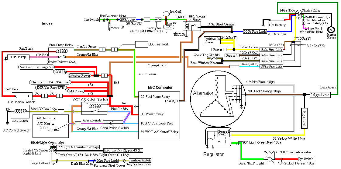
diagram courtesy of Tmoss & Stang&2Birds
fuel-alt-links-ign-ac.gif


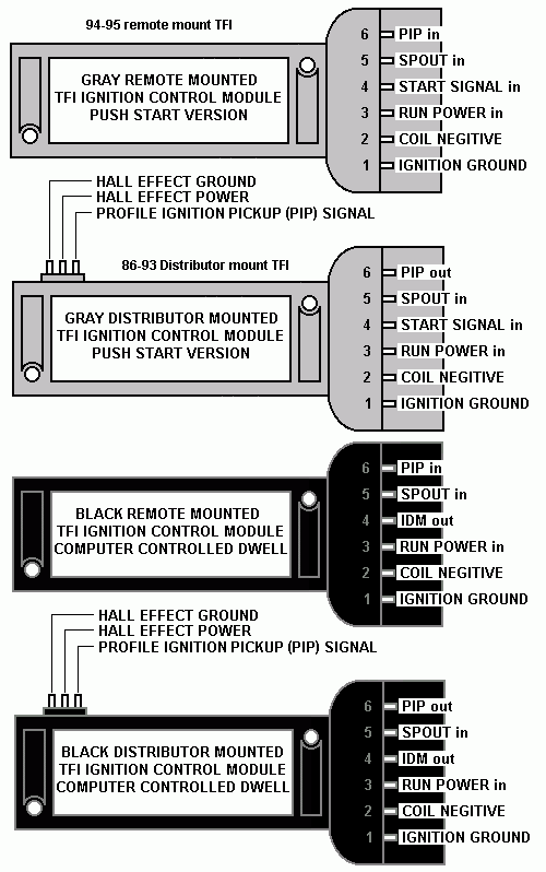
TFI_5.0_comparison.gif


TFIModuletroubleshooting.jpg


See the following website for some help from Tmoss (diagram designer) & Stang&2Birds (website host) for help on 88-95 wiring http://www.veryuseful.com/mustang/tech/engine/ Everyone should bookmark this site.

Ignition switch wiring
http://www.veryuseful.com/mustang/tech/engine/images/IgnitionSwitchWiring.gif

Fuel, alternator, A/C and ignition wiring
http://www.veryuseful.com/mustang/tech/engine/images/fuel-alt-links-ign-ac.gif

Complete computer, actuator & sensor wiring diagram for 88-91 Mass Air Mustangs
http://www.veryuseful.com/mustang/tech/engine/images/88-91_5.0_EEC_Wiring_Diagram.gif

Vacuum diagram 89-93 Mustangs
http://www.veryuseful.com/mustang/tech/engine/images/mustangFoxFordVacuumDiagram.jpg

HVAC vacuum diagram
http://www.veryuseful.com/mustang/tech/engine/images/Mustang_AC_heat_vacuum_controls.gif

TFI module differences & pinout
http://www.veryuseful.com/mustang/tech/engine/images/TFI_5.0_comparison.gif
 
That is useful in that it does not point to fuel problems . That takes us back to the ignition system. I would suspect that the TFI module is the most likely source of your problem, followed by the PIP sensor in the distributor.

The no start condition may actually turn out to be helpful in narrowing down the choice of TFI or PIP sensor.

just replaced the tfi sensor and the problem is still there..
 
oops didnt mean to put it in a quote..

just replaced the tfi module and spark plugs, should i do plug wires, cap and rotor, and coil?

Do a cylinder balance test to eliminate any weak cylinders.

Cylinder balance test: use this to find dead or weak cylinders:

Revised 19-Dec-2015 to update RPM ranges and include a more complete description of the engine running tests that are done prior to the cylinder balance test. Added YouTube video to show the process.

The computer has a cylinder balance test that helps locate cylinders with low power output. You’ll need to dump the codes out of the computer and make sure that you have the A/C off, clutch depressed to the floor and the transmission in neutral. Fail to do this and you can’t do the engine running dump codes test that allows you to do the cylinder balance test.

Here's the way to dump the computer codes with only a jumper wire or paper clip and the check engine light, or test light or voltmeter. I’ve used it for years, and it works great. You watch the flashing test lamp or Check Engine Light and count the flashes.

Be sure to turn off the A/C, have the clutch depressed to the floor, and put the transmission in neutral when dumping the codes. Fail to do this and you will generate a code 67 and not be able to dump the Engine Running codes.


Here's how to dump the computer codes with only a jumper wire or paper clip and the check engine light, or test light or voltmeter. I’ve used it for years, and it works great. You watch the flashing test lamp or Check Engine Light and count the flashes.

Underhoodpictures007-01.jpg


Underhoodpictures010.jpg


If your car is an 86-88 stang, you'll have to use the test lamp or voltmeter method. There is no functional check engine light on the 86-88's except possibly the Cali Mass Air cars.

attachment.php?attachmentid=58312&stc=1&d=1242744354.gif


The STI has a gray connector shell and a white/red wire. It comes from the same bundle of wires as the self test connector.

89 through 95 cars have a working Check Engine light. Watch it instead of using a test lamp.

attachment.php?attachmentid=57945&stc=1&d=1240584741.gif


The STI has a gray connector shell and a white/red wire. It comes from the same bundle of wires as the self test connector.


WARNING!!! There is a single dark brown connector with a black/orange wire. It is the 12 volt power to the under the hood light. Do not jumper it to the computer test connector. If you do, you will damage the computer.

What to expect:
You should get a code 11 (two single flashes in succession). This says that the computer's internal workings are OK, and that the wiring to put the computer into diagnostic mode is good. No code 11 and you have some wiring problems. This is crucial: the same wire that provides the ground to dump the codes provides signal ground for the TPS, EGR, ACT and Map/Baro sensors. If it fails, you will have poor performance, economy and drivability problems

Some codes have different answers if the engine is running from the answers that it has when the engine isn't running. It helps a lot to know if you had the engine running when you ran the test.

Dumping the Engine Running codes: The procedure is the same, you start the engine with the test jumper in place. Be sure the A/C is off, clutch depressed to the floor and the transmission is in neutral. You'll get an 11, then a 4 and the engine will speed up to do the EGR test. After the engine speed decreases back to idle, it will dump the engine running codes.

Trouble codes are either 2 digit or 3 digit, there are no cars that use both 2 digit codes and 3 digit codes.

Your 86-88 5.0 won't have a working Check Engine Light, so you'll need a test light.
See AutoZone Part Number: 25886 , $10
4.jpg


Alternate methods:
For those who are intimidated by all the wires & connections, see Actron® for what a typical hand scanner looks like. Normal retail price is about $30 or so at AutoZone or Wal-Mart.

Or for a nicer scanner see www.midwayautosupply.com/Equus-Digital-Ford-Code-Reader/dp/B000EW0KHW Equus - Digital Ford Code Reader (3145It has a 3 digit LCD display so that you don’t have to count flashes or beeps.. Cost is $22-$36.


Cylinder balance test

If you have idle or IAC/IAB problems and the engine will not idle on its own without mechanically adjusting the base idle speed above 625-750 RPM, this test will fail with random cylinders pointed out every time it runs. The IAC/IAB must be capable of controlling the engine speed to run in the 1300-1500 RPM range. Playing with the base idle speed by adjusting it upwards will not work, the computer has to be able to control the engine speed using the IAC/IAB.

Warm the car's engine up to normal operating temperature. With the test jumper in test position, start the engine and let it stabilize. It should flash a 10 and then a 4 and maybe an 11. If no 11, then there are other codes that will be dumped.
One of the first tests it does is to open the EGR all the way, this will cause the engine to stumble and almost die. If the engine dies here then you have EGR problems.
To start the cylinder balance test, briefly floor the accelerator past 2500 RPM and let off the accelerator. The engine will stabilize at about 1300-1450 RPM and the cut off the fuel injectors one at a time. The engine speed will drop briefly and the computer will turn the fuel injector for the cylinder under test back on. Then it starts the process for the next cylinder. When it has sequenced through all 8 injectors, it will flash 9 for everything OK, or the number of the failing cylinder such as 2 for cylinder #2. Quickly pressing the throttle again up to 2500 RPM’s will cause the test to re-run with smaller qualifying figures.
Do it a third time, and if the same cylinder shows up, the cylinder is weak and isn’t putting out power like it should. See the Chilton’s Shop manual for the complete test procedure

See
View: https://www.youtube.com/watch?v=HDXrkKS4jTE
for a visual tour through the process. There is no voice narration so you have to listen carefully for the engine sounds.

Do a compression test on all the cylinders.
Take special note of any cylinder that shows up as weak in the cylinder balance test. Low compression on one of these cylinders rules out the injectors as being the most likely cause of the problem. Look at cylinders that fail the cylinder balance test but have good compression. These cylinders either have a bad injector, bad spark plug or spark plug wire. Move the wire and then the spark plug to another cylinder and run the cylinder balance test again. If it follows the moved wire or spark plug, you have found the problem. If the same cylinder fails the test again, the injector is bad. If different cylinders fail the cylinder balance test, you have ignition problems or wiring problems in the 10 pin black & white electrical connectors located by the EGR.

How to do a compression test:
Only use a compression tester with a screw in adapter for the spark plug hole. The other type leaks too much to get an accurate reading. Your local auto parts store may have a compression tester to rent/loan. If you do mechanic work on your own car on a regular basis, it would be a good tool to add to your collection.

With the engine warmed up, remove all spark plugs and prop the throttle wide open with a plastic screwdriver handle between the throttle butterfly and the throttle housing. Crank the engine until it the gage reading stops increasing. On a cold engine, it will be hard to tell what's good & what's not. Some of the recent posts have numbers ranging from 140-170 PSI. If the compression is low, squirt some oil in the cylinder and do it again – if it comes up, the rings are worn. There should be no more than 10% difference between cylinders. Use a blow down leak test (puts compressed air inside cylinders) on cylinders that have more than 10% difference.

I generally use a big screwdriver handle stuck in the TB between the butterfly and the TB to prop the throttle open. The plastic is soft enough that it won't damage anything and won't get sucked down the intake either.

A battery charger (not the trickle type) is a good thing to have if you haven't driven the car lately or if you have any doubts about the battery's health. Connect it up while you are cranking the engine and it will help keep the starter cranking at a consistent speed from the first cylinder tested to the last cylinder.
 
Also the car was switched to MAF if that makes a difference? I can post pictures of the engine bay and or anything else that would be helpful if needed. Thanks!

Take a look at your O2 harness down by the pass fender near the WOT relay (under the MAF). Is there a jumper in the harness? The connector is an 8-pin connector. Do you see 8 wires in the plug, or 5?

Reason I ask is that 1987's lack three wires in this harness that are needed for the MAF conversion that aren't well known. Ford routed the wiring for the NSS there starting in 1988. 1987 cars have been known to not run well unless the harness is changed out to the 1988+ engine harness.


However, I'd sort through the codes first. Looks like you have a code for the EGR valve, and charcoal canister. Are those present on the car or did someone yank them off?

Code 95 is caused by not hooking up the fuel pump relay wire when the MAF conversion is done. This one can be ignored, as the car does run.

I'd venture to guess the VSS wiring may not have been hooked up as well? The VSS is used by MAF cars to prevent stalling when coming to a stop. if you have this issue, or engine idle issues when pushing in the clutch coming to a stop, you'll want to investigate if the MAF computer was wired to the VSS. (vehicle speed sensor)
 
Did the balance test twice and it came back with reading #9 each time

The egr valve and canister seem to both be missing! Found a wire and harness under the MAF that has 5 wires but nothing with 8.

Any thoughts? Also while doing the codes again I discovered the engine running code of 21 has been added to the 94, 31, and 44.
 
If you run the codes with the engine cold, you always get code 21. Ignore it for now. Rerun codes with warm engine and it should go away.

31 44 and 94 pertain to all your deleted smog eauipment. Smog pump, egr, charcoal canister etc.

How modded is your car?


Sent from my big ass iPhone 6 using Tapatalk
 
Mod list Of what's done to the engine:

Pro Comp aluminum heads
Edelbrock Performer RPM II upper & lower
new lifters
New rockers
New pushrods
E303 cam
Champion 3 row aluminum radiator
new hoses
Shorty headers with h-pipe & Flowmaster Super 44's
Upgraded to MAF & 130 amp alternator with all new wiring kit & Optima yellow top battery. Walbro 255 fuel pump
fuel sending unit
Aeromotive fuel regulator


The regulator always reads 0 and I also changed the plugs and they were all showing signs of running really rich. Seemed like the car was pretty warm I let it run for 5 mins before I did the test!
 
Code 21 is the engine coolant temp sensor. Get the engine warm again and rerun the codes. If you get 21, replace the ect. It could be your issue.

As for the wiring differences on a 1987, this isn't fully understood yet. Basically your engine harness lacks three wires for the NSS that mass air cars have. Whether or not this is needed is not understood yet, but some have claimed 87maf conversions hard to tune until they swapped to an 88+ engine harness


Sent from my big ass iPhone 6 using Tapatalk
 
Code 21 is the engine coolant temp sensor. Get the engine warm again and rerun the codes. If you get 21, replace the ect. It could be your issue.

As for the wiring differences on a 1987, this isn't fully understood yet. Basically your engine harness lacks three wires for the NSS that mass air cars have. Whether or not this is needed is not understood yet, but some have claimed 87maf conversions hard to tune until they swapped to an 88+ engine harness

just tested it again and code 21 is gone now, any ideas?