Electrical Weak spark on #1 cylinder. Suggestions/Help

MrBottleneck

Member
Sep 12, 2018
37
21
18
Ohio
Ok, so, my car has a slight stumble at acceleration and so after hunting around I found the #1 cylinder spark is testing weak (very faint spark)
I actually came across this by accident by way of the timing light. So, I proceeded to hook the light to all cylinders to see if it would trigger light and it did.
(I must add the engine is original and healthy with 40,000 original miles and compression is fantastic in all cylinders)
I can faintly see the spark in the spark tester on #1 cylinder. All the other cylinders are ok and light up the spark tester lit up brightly.
I switched the wires from the adjacent cylinder with #1 at plug/cap to rule out bad wire and it’s not the wire. It’s so weak it won’t trigger the timing light to flash as I mentioned.

Weird thing is upon cranking I get the normal bright spark on that cylinder like all the other cylinders (about three bright sparks) but, once it starts and runs it’s very faint.
The distributor cap appears fine although I have not gone throwing parts at it.
I have checked continuity from inside of cap on #1 cylinder to outside and it’s fine.

Could it be the PIP sensor causing this?
Suggestions?


PS: I have checked compression in all the cylinders and they 175-180 (lowest to highest three are at 175, two are at 178 and three are at 180)
I have also done a cylinder balance test that came back ok.
There is no cel and are no codes related to this.

Help or suggestions much appreciated. :)
 
Last edited:
  • Sponsors (?)


Ok, so, my car has a slight stumble at acceleration and so after hunting around I found the #1 cylinder spark is testing weak (very faint spark)
I actually came across this by accident by way of the timing light. So, I proceeded to hook the light to all cylinders to see if it would trigger light and it did.
(I must add the engine is original and healthy with 40,000 original miles and compression is fantastic in all cylinders)
I can faintly see the spark in the spark tester on #1 cylinder. All the other cylinders are ok and light up the spark tester lit up brightly.
I switched the wires from the adjacent cylinder with #1 at plug/cap to rule out bad wire and it’s not the wire. It’s so weak it won’t trigger the timing light to flash as I mentioned.

Weird thing is upon cranking I get the normal bright spark on that cylinder like all the other cylinders (about three bright sparks) but, once it starts and runs it’s very faint.
The distributor cap appears fine although I have not gone throwing parts at it.
I have checked continuity from inside of cap on #1 cylinder to outside and it’s fine.

Could it be the PIP sensor causing this?
Suggestions?


PS: I have checked compression in all the cylinders and they 175-180 (lowest to highest three are at 175, two are at 178 and three are at 180)
I have also done a cylinder balance test that came back ok.
There is no cel and are no codes related to this.

Help or suggestions much appreciated. :)
Hi,
Open the Dizzy, clean any rust on the shutter wheel, clean up any corrosion on the Cap posts and internals, Rotor, & blast out the bowl with CRC MAF cleaner. Reterminate all your wires on the cap using electrical conductivity grease.
Remove your block ground & clean it up, retorque.
Same with the block to Chassis strap.
Try after that, see if it helps. If not, fire the car off in the dark & look for any arcing that may be occurring. If nothing, try the below...
Verify advance with a light & label and move all your wires over one position on the Cap to isolate things further, (First mark the Dizzy as-is with a sharpie at the original timing position to the hold down clamp).
Once it fires, retime it & see if the weak spark indeed migrates to the next cylinder, and #1 begins to fire off normally, or if it remains there.
Best of luck!
-John
 
Ok, did all the above distributor clean out etc.
New cap and rotor and plugs.

Still weak spark at #1 BUT, if I unplug the spout connector at TFI/distributor harness walla I have strong spark there at #1.

So, ? Ideas ? TFI module ?

PS:
With spout unplugged timing was set like at 23* lol ? ? so, being I can get timing light flash with spout unplugged on #1 (and that’s what you have to do anyhow) I set timing to 12*
Now, the only way I could verify computer was advancing timing was by to going to next adjacent plug wire and unplugging spout then plugging in to see change. It is being advance by computer as it should.

Thanks and If you take the time to help double Thanks. :)
 
Last edited:
Ok, did all the above distributor clean out etc.
New cap and rotor and plugs.

Still weak spark at #1 BUT, if I unplug the spout connector at TFI/distributor harness walla I have strong spark there at #1.

So, ? Ideas ? TFI module ?

PS:
With spout unplugged timing was set like at 23* lol ? ? so, being I can get timing light flash with spout unplugged on #1 (and that’s what you have to do anyhow) I set timing to 12*
Now, the only way I could verify computer was advancing timing was by to going to next adjacent plug wire and unplugging spout then plugging in to see change. It is being advance by computer as it should.

Thanks and If you take the time to help double Thanks. :)
Hi,
No problem! We’re all there at one time..:bang:
Or another..!lol.
-Did you run down the Stangnet ‘Crank but no Start’ checklist? Great info, excellent place to start, will help- now or in the future.
Is this a new purchase, what year is it?
Since we’re moving, might as well keep the ball rolling...
Did you attempt to retrieve any Codes? May be there without a CEL..
Few thoughts..Find a helper...
1) Check the voltage feeding your Coil’s primary when Cranking and when running. Grab a spark tester and clamp to the Block or other clean, Conductive surface & see if you get a nice spark that will jump 3/8”-1/2” gap from a few random cylinders, cranking & running. May be weak to begin with.
2) Grab a Jumper Cable & add it from Battery to Block as a temporary ground, make sure it’s solid, will help with the test. Grounds being solid cannot be overstated.
3) Have any aftermarket ignition components, e.g. Coil, TFI, Dizzy, etc? All show & first to go. Prime suspects...
4) TFI’s can be tested at most Auto Chain stores, worth testing & re-install apply ample heat sink compound to a Hospital clean surface. Although not 100%, TFI’s usually fail- completely, or may have problems when at excessive Temperatures..
This occurs in both Cold & Hot conditions?
5) Did you (temporarily) shift the wires on the Dizzy Cap & retime to verify it is/is not isolated to the #1 Cyl..(per last text) or migrates to another Cyl.?
X— PIP sends signal to EEC, EEC to TFI, SPOUT removal breaks to connection for EEC controlled timing assist.
6) You mentioned 23 Deg Timing advance at idle was set? Some run no SPOUT & Advance idle timing into 26-32 Degrees, that’s where it’ll stay. Though It works, bad idea- however. Can be setup correctly to, but risks outweigh benefits.Car have a SPOUT when purchased?
7) The PIP is sensing the Shutter wheel, other cylinders are firing, small chance it’s not picking up #1 Cyl for long enough, this is all cleaned up, no Rust, moisture, Corrosion? Test moving wires will help isolate this.
8) Battery Voltage >/=12.0VDC, Charging system strong (12.7-13.7VDC Alternator output when running?
9) Check that your Distributor I Grounded to the Block, Battery. Some O-ring lubricants, Grease when installing the Dizzy can interrupt this. Simple VOM Resistance check, Battery(-) to Dizzy Chassis.
9) This is likely a simple repair, PIP functions, EEC increases Spark Dwell during Cranking, TFI’s
10) Is the engine stock, or have Bolt-on’s, good Engine Pic =1,000 words.
Hope that helps, best of luck!
-John
 
Hi,
No problem! We’re all there at one time..:bang:
Or another..!lol.
-Did you run down the Stangnet ‘Crank but no Start’ checklist? Great info, excellent place to start, will help- now or in the future.
Is this a new purchase, what year is it?
Since we’re moving, might as well keep the ball rolling...
Did you attempt to retrieve any Codes? May be there without a CEL..
Few thoughts..Find a helper...
1) Check the voltage feeding your Coil’s primary when Cranking and when running. Grab a spark tester and clamp to the Block or other clean, Conductive surface & see if you get a nice spark that will jump 3/8”-1/2” gap from a few random cylinders, cranking & running. May be weak to begin with.
Will check
2) Grab a Jumper Cable & add it from Battery to Block as a temporary ground, make sure it’s solid, will help with the test. Grounds being solid cannot be overstated.
OK
3) Have any aftermarket ignition components, e.g. Coil, TFI, Dizzy, etc? All show & first to go. Prime suspects...
None of ignition stuff is aftermarket. Mostly actually original 31 year old parts. Cap, Rotor, Plugs, and Wires all new Motorcraft.
4) TFI’s can be tested at most Auto Chain stores, worth testing & re-install apply ample heat sink compound to a Hospital clean surface. Although not 100%, TFI’s usually fail- completely, or may have problems when at excessive Temperatures..
This occurs in both Cold & Hot conditions?
Will get checked, and the weak spark at #1 is anytime all the time when spout eis in.
5) Did you (temporarily) shift the wires on the Dizzy Cap & retime to verify it is/is not isolated to the #1 Cyl..(per last text) or migrates to another Cyl.?
Have not moved and re stabbed distributor yet moving over firing order one BUT, swapped wires and it’s not wire issue.
X— PIP sends signal to EEC, EEC to TFI, SPOUT removal breaks to connection for EEC controlled timing assist.
6) You mentioned 23 Deg Timing advance at idle was set? Some run no SPOUT & Advance idle timing into 26-32 Degrees, that’s where it’ll stay. Though It works, bad idea- however. Can be setup correctly to, but risks outweigh benefits.Car have a SPOUT when purchased?
Yes, spout was in when at 23* so, pulled and set to 12*
7) The PIP is sensing the Shutter wheel, other cylinders are firing, small chance it’s not picking up #1 Cyl for long enough, this is all cleaned up, no Rust, moisture, Corrosion? Test moving wires will help isolate this.
As mentioned haven’t moved firing order on distributor to see if issue migrates but, I have cleaned out distributor bowl etc. Some dust/dirt fine stuff nothing major.
8) Battery Voltage >/=12.0VDC, Charging system strong (12.7-13.7VDC Alternator output when running?
Pretty sure I checked it but, will reverify. I am almost sure it good though.
9) Check that your Distributor I Grounded to the Block, Battery. Some O-ring lubricants, Grease when installing the Dizzy can interrupt this. Simple VOM Resistance check, Battery(-) to Dizzy Chassis.
Distributor hasn’t been pulled but, will check with VOM.
9) This is likely a simple repair, PIP functions, EEC increases Spark Dwell during Cranking, TFI’s
10) Is the engine stock, or have Bolt-on’s, good Engine Pic =1,000 words.
CAR has 40,089 original miles in stellar condition. Previous short time owner after original purchaser for what ever reason yanked off stock TB and spacer and installed a cheap sticky and rough SVE TB and Spacer. I put original back on (Came with car) after thoroughly cleaning etc. Much smoother.
Same with CAI guy put on an elcheapo CAI so, that came off and original went back on alone with new Motorcraft filter.
Other then that car has headers and catless H.
Everything else bone stock original.
I did put as mentioned new Motorcraft: Cap, Rotor, Wires, Plugs and Fuel Filter on car.
I also, replaced Radiator because it was leaking ( had small hole) and I have yet to find a manual NOS rad or someone willing to re-core original. The one in there isn’t meant to be permanent imho. While I had it all apart I put all new Motorcraft Hoses and the SERP belt on and did the Water Pump with new as well just because the old stuff was OE and showing it.

I also have a new Ford stock MAF Sensor coming that was last one left at any dealer in US. Never know if I might need it sometime.


Thanks for adding input it’s greatly appreciated and I will be check on the things you have mentioned that I have yet to do.
Here is engine of car Pic as requested.


Hope that helps, best of luck!
-John
 

Attachments

  • 22C430EB-D783-4466-87E1-BE0B6CF9E0CB.jpeg
    22C430EB-D783-4466-87E1-BE0B6CF9E0CB.jpeg
    425.5 KB · Views: 147
Last edited:
  • Like
Reactions: 1 user
Hi,
Very clean! Wanted to say the test #5 can be bypassed, it’s more of an initial test to isolate an issue, the diagnostic efforts youre now pursuing will do the same & more.
Looking forward to what you find, move on if needed.
Good luck!
-John
 
Ok, done tons of testing on system wiring, TFI and etc and I think I might have found the culprit.
We will soon see.

Anyhow one of the capacitors as pictured has the green fuzz/blob of death from my untrained eyes.
The one leg on the one capacitor looks nothing like the other un-green legs as they all look like nice clean silver solder.

I haven’t received the redone/new capacitors A9L yet so, I am kinda hoping this is issue.
If not the hunt for the culprit will continue but, surely this leaking capacitor could cause an issue.

Does anyone know specifically what circuit the capacitor in question relates too?

In the first picture you can see the clean leg of capacitor.
Second picture shows green blob on other leg.
Third pic is capacitor in question.
 

Attachments

  • 0C5B358B-1013-4254-A6E3-365C6D8C0269.jpeg
    0C5B358B-1013-4254-A6E3-365C6D8C0269.jpeg
    330.7 KB · Views: 140
  • 1DD88396-8A80-4EA9-9BB0-40AAA4A1771C.jpeg
    1DD88396-8A80-4EA9-9BB0-40AAA4A1771C.jpeg
    170.1 KB · Views: 146
  • F444CD52-1899-42B9-82A6-2BF15B2CF31D.jpeg
    F444CD52-1899-42B9-82A6-2BF15B2CF31D.jpeg
    517.2 KB · Views: 144
Ok, done tons of testing on system wiring, TFI and etc and I think I might have found the culprit.
We will soon see.

Anyhow one of the capacitors as pictured has the green fuzz/blob of death from my untrained eyes.
The one leg on the one capacitor looks nothing like the other un-green legs as they all look like nice clean silver solder.

I haven’t received the redone/new capacitors A9L yet so, I am kinda hoping this is issue.
If not the hunt for the culprit will continue but, surely this leaking capacitor could cause an issue.

Does anyone know specifically what circuit the capacitor in question relates too?

In the first picture you can see the clean leg of capacitor.
Second picture shows green blob on other leg.
Third pic is capacitor in question.
Hi,
I’m not seeing what you mean, an electrolytic Capacitor is generally held on with a few tacks of glue, to hold them in place by a few dabs of glue for a mechanical connection, then soldered to the PCB by its (+) or (-) polarity is very important with caps, and when they will explode.
Always wear goggles and/or a dace shield, the fluid inside is boiling hot when it hits you)
Is there a bubble forming on the Cap anywhere. Or evidence it was hot... ?whatever the circuit it’s in, the voltage is generally double of that which it’s within.... 12V circuit= 24V Cap.
Multiple types of Caps available, use care around them, the electrolytic- like you’re showing, like to explode if shorted o
I see a Zener Diode and a Eesistor both in one pic. Too
Were is the leakage you’re seeing? Either way..place your PCB on the cap on a ground mat, (20-30$, well worth it,) static kills Transistorscand most other components, they’re rated for a few bolts. Static may be in tens of thousands- poof! that fast.
#1 reason rechipping fails...static destroying components.
 
Hi,
I’d Zoomed in a bit, It’s leeching indeed. I use helping hands (adjustable alligator clips affixed to a base) (& a magnifying glass works just fine) or a small wireless electronic zoom/focus camera with adjustable light output (tiny, WIFI’s to your phone- 20X to 100X- uses your cell as a screen) locates damaged or melted PCB traces, closely and slowly both sides of the PCB, easy to miss, take your time.
Buy a little Tin of solder paste.quick wipe of the guns tip to the wet sponge. Dip the iron’s tip in the paste...
Repair with a #18-#22AWG THHN insulated wire jumper. Wherever/before you solder, Be sure to remove any board shellac coating residue using rubbing alcohol applied a Q-Tip, use care not to disturb(lift) traces..
I replace all Electrolytics in these EEC’s, only 4-5, at- 25 yrs old, certainly in need of replacing. .
(Do NOT skimp on quality when replacing or any component; Cap. Don’t replace with ‘Capexon’ electrolytic Capacitors, they use them in many lot of the cheap TV’s today, to cut prices. Talking a 1$ difference, adds up for cheap Mfg’s. Usually back lighting that fails.
470uF(or 47-Verify!) 16V Electrolytic Caps are easy to find, I use Digi-Key or Mouser when buying all mug electronic components,
1) Use A pencil type iron/soldering station & a Sponge(keep wet). Voltage of a Cap must be as high (usually twice the Voltage of an App.) 60-40 1/32” Rosin core Solder, a small red solder sucker-bulb. Squeeze- apply gun h
A ‘ Nichicon’ or ‘Sprague‘ are both good, reliable brands, there’s other good brands, cost needs not be high for good quality.
Radio Shack’s brand isn’t bad either. I use a dab of hot melt glue to keep the load off the legs. Prevent it from moving.
I generally use to Digikey or Mouser for all semiconductors, general electronic components , high quality ,with a sponge & holder
Solder, a red oval solder sucker- white tip to shake out the chunks when you’re done. Patient Cr, cut the legs as close to the Cap as you can, so you need only pull out the pins, clean out the solder where you remove them. Scrape a little bit off the trace for good solder adhesion, you’ll be just fine, I’m
370-040_HR_0.jpg
. Keep your soldering gut tip clean with the wet sponge;m(rotate it while dragging towards you.
If look at your J-3 Connector closely...was it chipped? Seems very worn, traces lost..... can you get a pic of the other side of it, ?
Pics...BEST SOLDER SUCKER. Buy (2), 3-5$ apiece- BEST for your Application..!!!!!3-5$$..
BF607321-5854-401C-9583-45CD3FFDA10D.jpeg
BEST, CHEAP, WORKS GREAT!! Get a practice PCB, try it. Squash it, if you have Capacitor legs. Cut off so max length, heat up legs where they meet the PCV, add a teeny bit of the tin containers flux w lsolder $ the legs will come right out. Quickly put the clean solder Gus tip to the Use the squashed sucker’s white plastic hole aimed at the hot solder & release. It’ll suck the molten solder out


WASTE OF MONEY!!

5656C45E-41AF-4895-BA44-875C0A3BB46E.jpeg
Below may work, higher likelihood of MORE WASTED MONEY!


2A94F016-4530-4556-8F9C-6D7BDAF2D95D.jpeg
NOT good for your APP. Rubber solder sucker is optimal, HEATbis the enemy, this creates FAR too much, Costly.

Hope this helps. Please post any questions!
Best of luck!
Practice first, then go after this.
-John
 
“If look at your J-3 Connector closely...was it chipped? Seems very worn, traces lost..... can you get a pic of the other side of it, ?“

Glad you could see it. I actually took a dental pic and the green scale would kinda just just flake off that area so, there’s no doubt it had leaked. It was like a powdery scale.

I am not sure where there J3 connector your talking about resides within the PCM. Can you point it out so, I can check what you are referring too?
I can get you pictures of the backside of board later today no problem.

Would I be better to jest send the PCM off to a company and have them go through it?

I found this guy on EBAY that sells the capacitors.
http://rover.ebay.com/rover/1/711-5...0001&campid=5335821607&icep_item=352446543989

What do you think the odds are of this being my problem I have been trying to find?
Do you have any idea what this capacitors function as far as what exactly it does in the working function of the PCM?

Thanks for you help and input as well.
 
We just went through this with another member. Theres a pickup and a window assembly below the cap rotor button. This is what the computer uses to detect number 1. If you remove the cap you can shine a light down there and see the pickup.

It shouldn't look powdery or disintegrated. The windows should look like clean metal and not rusty. I've rebuilt multiple distributors and it isn't very complicated if you have a small press to take the gear off the bottom and press it back on.

The computer should be sent off anyway just to replace the caps and stuff that we know will go bad.
Yes, I am more then aware of the Hall Effect Sensor “aka PIP” (basically a crank sensor) inside the distributor. I had already looked at that.
But, I am pretty sure if that was bad it’s bad it wouldn’t be effected by removing and installing spout which is what is determining whether I have good spark at #1.
Number #1 is recognized by PCM by the smaller vane on the trigger wheel that passes through PIP.
 
  • Like
Reactions: 1 users
Hi,
I’d Check the below, if done- move on. Decide if replacing EEC Cap’s is what you want to do..
, I’ve seen that-specific Cap fail and similar issues to what your experiencing occur, EEC should have been “self tested”, a code 11 is the “all clear” EEC status.
- I’ve also seen the SPOUT pins/socket Oxidized, spray with CRC electrical cleaner, tighten pins up.
- A loose wire test Also do it, a Tug test is another good check.
-A PIP issue if an OE type usually works or not, generally affects injectors and Ignition, but doesn’t follow rules.
-Grounds or intermittent problems are difficult to pin down.
- The 2 salt & pepper shakers both have EEC wires crucial passing throug, pull apart, clean well, tighten up loose pin(s) gently with a ‘“small jewelers screwdriver.
The EEC is enerally he last spot you would seek out an issue, if troubleshooting leads you there, it is what it is, IMO, I wouldn’t purchase electronic components from EBay any more than a rebuilt engine, but that’s your Call- I’d message the seller & jot down theitalled Electrolytic Cap values and Mfg, source, see if they’re properly sealed, packaged, view buyer commen
Digi-Key or Mouser electronics.
-Digi-Key will stock the Electrolytic Cap’s you need with no minimum.
May be 50-75 cents each + Shipping, which can combined.
Capacitor substitution.
In some (few exceptions) circumstances you may utilize a higher Voltage rating than
on the nomenclature of replacement Electrolytic Cap’s safely in use.In THIS (your). instance, is an example where you can utilize a higher.Voltage.
NEVER substitute any Capacitor with a higher/lower Voltage or other rating(s) than identical labels l what you’re replacing, unless you have the electronic diagram. and clearly understand what you’re reading.The SAME part values are non Capacitance (Microfarads). The voltage (16V) (110 Degrees Celsius), and tolerance (20%).
Digi-Key: CAP ALUM 47UF 25V 20% RADIAL P/N # P14411-ND
Soldering on a PCB...
As bad solder joints- or leaky, overheated or old Electrolytic Cap’s begin to fail, it may no longer provide the correct value(S) reflected on rated in Milli, Nano, Micro, Pico- portions of a FARAD, as the VALUE required is sized significantly LESS than (1) Farad. Just FYI.

OBD-0,OBD-1, OBD-2 EEC’s....
Many older CPU’s and similar
sensitive equipment ran large electrolytic capacitors to maintain balance in various DC power circuits to smooth out ‘surges and spikes’ to a minimum & provide clean “ripple free” Voltage prior to implementation of more modern IC regulators, other modern components which are necessity in newer Digital circuits requiring very clean now utilized.
Electrolytic capacitors being one of the methods utilized in the 80’s, early 90’s in maintaining clean DC power with minimal surges and spikes, used in injectors, ignition, sensors,& 02 circuits regulated under heavy demand.
Replacing the Components on the PCB
You can surely replace the Cap’s on your own carefully and noting polarity with a small pencil iron (<40W) with a wet sponge, a small can of tip cleaning Flux, a and solder sucker, a few small picks & micro pliers, not terribly difficult to execute - but one oversight- very unforgiving.Too much heat may migrate- damaging nearby components, lift traces, etc..Too little contaminates new joints, may not conduct electricity correct (“Cold Solder joint”) may connect things not intended to be, destroying a CPU.Hard to find, expensive.
Following board traces & seeking damage the traces to verify no existing damage has occurred is a tedious task, time consuming.
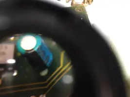
J3 Connector on your PCB.
I was viewing the J3 traces on the rear of the board where you’d install a chipset as it looked unusual, but it looks fine, still has the coating on the pins is all. These are cleaned off of all coating when when installing a chip.No Chip, leave it as is (FIGURE A).
Check your (60) Pun connector & make certain the pins fit snugly and no media exists, that will cause serious headaches.
A43737C5-A50E-4EF2-8F0D-934571288A0D.jpeg
FIGURE A (Above..J3 Connector)


I’d strongly consider sending it off to be repaired if you’re new to this.
It’s not difficult to perform, not doubting any abilities, but a simple error may cost you a Computer. Yes, all the Electrolytic Capacitors should be replaced,
I replace these when I rechip an EEC, and Electrolytic capacitors in all other CPU’s of the 80’s- mid 90’s Genre’,(OBD-1, not OBD-2).
There are certainly issues like yours caused by a bad PCB Capacitor. It’s an issue that should be repaired, then move forward with your troubleshooting, if the issue persists..
I’d suggest cleaning the SPOUT pins and socket, and also replace all the Electrolytic Capacitors on the PCB. Once it’s completed, do a self test to verify the EEC gives you a Code 11.(clear).
Doing the job yourself, or farming it out to someone that does this work frequently....
These Capacitor are 20+ yrs old and reassemble (if you feel comfortable in doing such, I’d order the parts from Digi-Key, and replace the Capacitor(s) yourself- it’s not difficult with the right tools.
It’s important to mention that although the removal and install is not difficult, Electrolytic Capacitors are very dangerous if the (+) and (-) polarity is not correct when installing , or the capacitors legs contact one another, Installed incorrectly, they will melt the traces on the circuit board & these Capacitors of type will highly likely explode, covering your face in boiling hot oil.
IF You’re Skilled in this area, options to keep costs down..

Any doubts whatsoever, just send it to one familiar with electronics work.- a local TV repair shop is easily capable of acquiring decent replacement capacitors and correctly replacing these, It’s Cheap insurance.
EEC’s are expensive. Practice and perfecting your skills while reading or watching actual learning materials, I suggest not relying on you Tube, many things are attempted and some performed right and others dead wrong- who’s to Grade which is right or wrong- nobody. Much smarter if you get a locatvTV repair Shop to do the work, or a Computer repair shop with the right tools, you can order the parts, or get a component total price list and compare is say </=10$, shipped- for all.
Ask him if you can watch if you want to get some pointers. Do t send it to be gone through, just replace the Caps. Get a can of canned air to blow off any media off the PCB, no oil- clean air. Used in electronics work.
Work on small circuits.that are single sided component boards, work your way up to dual sided component boards with surface mount components from anything. Practice Preparation, soldering and resoldering. Buy the cheap tools I’d listed. All you need.
If you are familiar with all aspects of the procedure, and have the tools to correctly perform the task, you take your time and verify parts and polarity/installation as correct when doing the job, if they are soldered in incorrectly, know the hazards involved.
I’d never purchase electronic components from EBay, only from a trusted professional level source as listed above.
I’m not questioning your abilities, not in the least, but why take achance-right ?
Walk into a shop and ask, you may be quite surprised in how easy it all is. They May have these in stock.
Electrolytic Capacitors &!Construction/Destruction, lol!
Electrolytic Capacitors are the only type that will explode, containing fluid that may cause burns. always wear eyes/face protection. Some Capacitors have a Bleeder Resistor across the Capacitor to slowly discharge it over a short period of time, (30 Minutes</=). Measure with a voltmeter.Some do-have bleeders, some don’t.

You may already know this, but just in case-....
They can store enough energy to kill is the voltage and current is adequate, l30V at 1/10th of an amp across the chest can cause a human heart to stop, or be thrown out of rhythm, which must be reset with a defibrillator by a Physician. This is a lethal Arrhythmia that may cause Cardiac arrest.


Below is the J3 Connector, is coated as should be until an alternative chip is installed and programmed for modifications made.

42635b7c-6e84-4cce-b771-423aaa901cb5-jpeg.jpg


b020c122-4f4c-402e-93b6-9f20e052cb0a-jpeg.jpg


EEC Connector pins, Visually Inspect for any worn or dirty connector or board connection issues, do not touch pins unless on an earth grounded mat with a Wrist strap. Use caution, pins are uncoated with shellac as on remaining board is for clean connector contact when installed.

I’d viewed your traces & saw it looked OK, but you must look yourself to be sure all is well,
Good luck, ask questions if uncertain, I’ll help how I can, others will likely bring up better points.
Best!
-John
 
Huh?
You can’t see the green puddle under capacitor? Look at other solder joints in picture just to left of capacitor and see how silver clean looking they are then look at green blob.
It’s hard to hold a magnifying glass and use phone to snap a photo. :crazy:
9744C95A-3071-4029-9442-4F18264CA4AC.jpeg
 
Well, I’m at a loss.
Replaced all three capacitors (two where just starting to leak it appears) in PCM still no spark at #1 with Spout jumper in but, good spark with spout jumper out. Computer does sell test etc and is obviously working.
I leaning towards next culprit being PIP but not positive. Kinda running out of things to check.

pic of old caps
BB55006A-CF54-4237-998A-53470598F599.jpeg
Ideas?