Progress Thread Finally got my first Fox Body - 1988 GT

Continuing....

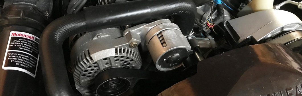
So I found that the orange/black alternator power cable thing does look like it runs in front of the radiator but on the starter solenoid side..seems a little weird. It looks like there’s another wire or cable that comes out on this end with it.
59A27693-656E-44ED-B280-0E3E8327846B.jpeg
Still trying to get the rest of the plastic wrap/protectant cover thing (and gobs of electric tape) from the orange/black power cable.

What I’m wondering now is, once I get that power cable out, do I run two separate “tunnels” from one side to the other, since the new power cable plastic cover/wrap thing doesn’t look like it has space for any other wires.
28234D86-A394-4188-99A5-329731655110.jpeg
 
  • Sponsors (?)


Just realized the yellow wire carries on with the orange and black cable...so the part where it connects before the starter solenoid makes more sense

4FAD4C22-CD9B-4A25-835C-6FC78E2CA296.jpeg
Still wondering the best way to wrap the rest of these wires between the alternator and the starter solenoid

497A83A1-1779-4F36-9FF3-EA3EBC47BBE7.jpeg
 
You can either run a second plastic loom around your new wire, or get some bigger loom and get it all into one.
I just took a quick look at my ‘86, and the orange/black green and yellow looks to be original wiring. I still have original style alternator.
Seems whoever did your 3g alternator upgrade skipped out on adding the thicker wire altogether!
Good move getting it sorted out!
 
  • Like
Reactions: 1 user
I'm glad you are doing this. That was a fire waiting to happen. There should be 2 black and orange wires. Neither of them are needed.

Edit; the wires are black and orange. I was multitasking.
 
Last edited:
  • Like
Reactions: 1 user
I'm glad you are doing this. That was a fire waiting to happen. There should be 2 black and read wires. Neither of them are needed.
Black and red? Where do they run between?

The yellow wire that runs from the alternator. Here’s a closer up shot of how it connects to the black orange wire just before the solenoid. Based on reading some other threads, I understand the yellow wire is important....but I’m not sure how I should go about making sure it’s connected once I remove it from this reverse splitter thing.

72CBA512-7DCD-412A-831E-22ADDB8DF3B7.jpeg
 

Check this thread out. There are full diagrams of what you should end up with. Some of it may have already been done with original install, but it should help you sort out what you have, and what you need to do.
 
That's a fusible link attached to the yellow wire below the rubber block thing. It's been a very long time since I rewired for my alternator. I meant to say black / orange....not red.

I shortened my alternator wiring. If you follow the green wire it goes to the drivers side corner below the booster....in that harness. Instead of running it around the mulberry bush I ran it down by the rack and up to the alternator.
 

Check this thread out. There are full diagrams of what you should end up with. Some of it may have already been done with original install, but it should help you sort out what you have, and what you need to do.
So I was actually already looking at that exact thread and I might be more confused now.

So in this diagram...it shows both the 4gauge to 3g alternator output and the 10 gauge black/orange wire. I thought the 4gauge was replacing the black/orange wire...and even if that was the case, I am still not sure what to do with the yellow wire, lol.

9ADEA662-4CF3-4D99-9021-0A0173C5A890.jpeg
 
The diagrams with the solenoid show wiring for both the 2g and 3g. Your new wire with the fuse would now be used and the black/orange is not.

Follow the diagram of the alternator and the descriptions of what each wire does, and where it goes. That explains it best.

I see with both in the same diagram why it may have been confusing.
 
  • Like
Reactions: 1 user
Like sickfox said it certainly looks like whoever upgraded the alternator did nothing to the original harness.
Good thing you're correcting this before any issues popped up.

Should be able to put to use that new multi wire stripper/crimper you got !
 
I appreciate you guys' patience in attempting to explain...since my brain is clearly struggling.

So I'm looking at the diagram that Rdub6 shared. I'm not sure I completely understand. On the alternator side, I get that the new 4 gauge power wire goes on the alternator output stud. And I see the regulator socket like in the diagram with three wires (green, yellow, and white) but on mine, the white wire goes from the regulator socket to what looks like the field winding power input(?).
IMG-9623.jpg
IMG-9624.jpg

Unless I'm looking at my alternator wrong and the white wire that is supposed to be spliced and crimped from the orange/black cable goes somewhere else?

Also, it doesn't look like my orange/black alternator power plug has that white wire coming off of it. Oh and it seems I only have one orange/black cable as opposed to the two it seems I'm supposed to have as shown in the diagram. Does it make sense why I'm confused? Lol. Here's another shot of the alternator power plug.
IMG-9625.jpg
 
Last edited:
Maybe they just used one of the orange/black as the power wire?
Right above your finger in the pic, does it look like a wire was cut? It was probably two, going into that factory splice where the thicker wire starts?
This is the frustrating part of trying to fix other people’s work that wasn’t done right.
But, as said by sickfox and steel, you’re correcting what could have been a major fire concern.
I would keep at it, even if you have to un-loom that whole harness to figure out what they have and where it’s going, and then get it to where it should be.
 
  • Like
Reactions: 1 users
Here is a pretty good article on the swap, in case you havnt found it yet.

 
  • Like
  • Hell Yeah!
Reactions: 1 users
The yellow wire is supposed to be a battery 12v sense wire for the alternator. The yellow wire goes to that rubber block...and then there should be a brown ( or some other neutral color ) wire that then ties into the black / orange to ( I think green ) the green wire then would connect to starter solenoid at firewall. Cut that brown wire as close to the junction as possible and add a ring terminal to it. That wire goes on the solenoid at the battery cable side.

That brown section of wire is the fusible link for the yellow wire.

The white / black wire is fine like that....that's how mine is ran. That white / black wire just normally would run from the three wire connector, up in the factory harness, and then loop back out.
 
  • Like
Reactions: 1 users
I’m pretty sure my original ‘86 wiring is different from the ‘87 and up. Maybe someone with the same year as yours can chime in with better descriptions of how it should be.
 
  • Like
Reactions: 1 user
The yellow wire is supposed to be a battery 12v sense wire for the alternator. The yellow wire goes to that rubber block...and then there should be a brown ( or some other neutral color ) wire that then ties into the black / orange to ( I think green ) the green wire then would connect to starter solenoid at firewall. Cut that brown wire as close to the junction as possible and add a ring terminal to it. That wire goes on the solenoid at the battery cable side.

That brown section of wire is the fusible link for the yellow wire.

The white / black wire is fine like that....that's how mine is ran. That white / black wire just normally would run from the three wire connector, up in the factory harness, and then loop back out.

Thank you. Just to confirm I am understanding you....am I looking at the right things? I circled the rubber block in yellow and the junction in red.

IMG-9613.jpg

So I can cut the yellow wire (after the rubber block, just before the junction) and then add a ring terminal and just connect it to the solenoid behind the ring terminal of the new power cable?
 
Cut the brown wire as close as you can to the junction you circled in red....add the ring terminal there. The fusible link ( brown wire ) is the fuse for the yellow wire. It needs to be a few inches long to work correctly. If you cut the yellow wire itself you'll need to add a fuse.
 
  • Like
Reactions: 1 users