charging problem

Graydon5oh

Member
Nov 23, 2002
215
0
16
ARKANSAS
ok i have a 93 lx hatch that was a 4cyl auto i have swapped it to a 50 5spd carb car
i extended the wires correctly using sauder have put a new altenator and battery on it and still i am not getting a charge and body got any ideas??
 
Are you using a 2G alternator? What are the voltage values you see at the regulator?
After a swap like that, it could be that your I terminal is not hooked up, or that A is not connected to battery voltage.

Good luck.
 
Tools needed: DVM (Digital Multi Meter) or multimeter, 1/2" wrench, 2 safety pins.
The safety pins are used to probe the wiring connectors from the wire side.
Make sure you know how to correctly use a DVM or multimeter.

Resistance checks:
Do not make resistance measurements with the battery ground lead connected. You will get
incorrect results and possibly damage the DVM or multimeter

Do not test the white/black wire at this time.
With the battery ground cable disconnected from the battery, use an ohmmeter to check continuity
on the wires. Turn the key to the Run position and place one ohmeter lead on the positive
battery cable and the other on each of the wires.

EDIT: All wires should read less than 1.5 oms, except the lt green/red wire, which should be 100-500 ohms

Testing the white/black wire:
Use the safety pins to probe the wiring connectors for the white/black wires or
disconnect them and probe the connector from the front side. You shoul see less than 1.5 ohms.

Voltage checks:
Carefully re-connect the battery cable postive termnial to the battery at this time.
Make sure that it is clean and tight
With tht stock alternator, you should see battery voltage (12 volts or more) on the black/orange,
yellow/white and lt green/red wires with the ignition switch in the run position. All measurements
are taken at the alternator.

No 12 volts on the black/orange wires - fuse link probably open
No 12 volts on lt green/red wire - dash indicator burned out, and 500 ohm resistor open circuited
No 12 volts on yellow/white wire - fuse link probably open

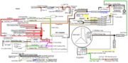
Diagram courtesy of Tmoss & Stang&2birds
fuel-alt-links-ign-ac.gif


See the following website for some help from Tmoss (diagram designer) & Stang&2Birds (website host) for help on 88-95 wiring http://www.veryuseful.com/mustang/tech/engine/ Everyone should bookmark this site.

Ignition switch wiring
http://www.veryuseful.com/mustang/tech/engine/images/IgnitionSwitchWiring.gif

Fuel, alternator, A/C and ignition wiring
http://www.veryuseful.com/mustang/tech/engine/images/fuel-alt-links-ign-ac.gif

Complete computer, actuator & sensor wiring diagram for 88-91 Mass Air Mustangs
http://www.veryuseful.com/mustang/tech/engine/images/88-91_5.0_EEC_Wiring_Diagram.gif

Vacuum diagram 89-93 Mustangs
http://www.veryuseful.com/mustang/tech/engine/images/mustangFoxFordVacuumDiagram.jpg
 

Attachments

  • fuel-alt-links-ign-ac.gif
    fuel-alt-links-ign-ac.gif
    83.1 KB · Views: 93
dash indicator? do you mean the gauge? and if so it isnt working also any
way to just wire this thing up to work?

The dash indicator is the battery warning light.

I recommend that you study the diagram I attached to the post, and consider how everything is wired together.
 
i believe my problem is with the resistor wire the one that says dash batt light on ur diagram because all the others seem fine so what do i need to do i have no clue what the stuff on that wire on that diagram are.... some one give me an idea how to fix this
 
1.) Does the battery warning light turn on when your turn the key to Run without the engine running?
If it does, then it is not a problem.

2.) Did you actually measure the voltage on the lt green/red wire?
If it does show 12 volts and the dash indicator lamp does not turn on, the light bulb is burned out
or loose in the socket.
If there is no 12 volts, then there are problems in the wiring.
 
ok i got u now, and iv got a question about it also i think when the white faces were done the amp gauge hand was placed to high could that affect its charging? and im fitsen to go check everything u said
 
A bad needle placement would not affect charging. It would be nice if it was that easy. Instead of buying an expensive upgraded alternator, we could just move the gauge's needle. :)

The chances of an issue with the resistor in parallel with the amp bulb is very unlikely IMHO.

Do your testing as JR outlined to figure things out quickly, rather than wasting time going off of bad testing (ensure your initial testing was correct before going down one road for too long). I learned that the hard way a long time ago.

Good luck.
 
ok the 2 black and orange wires are fine iv traced them all the way across there good have good connections the white wite that goes from plug to plug is fine also and the yellow wire runs int the loop with the black and orange so the green wire has to be my problem is there any way i can reg this wire to make it work so i can get it to the shop to be done correctly
 
Until you measure the voltage or resistance of the lt green/red wire, you cannot be sure it is the problem.
Do the testing first, then use the test results to guide you to what's broken instead of guessing.