Engine Cylinder balance results

John
, I have the comp cams push rod checker tool and also have the spring compressor depicted in figure two.
I have pretty much everything needed. so I assume I should bring the cylinder to be checked to top dead center and pressurize the cylinder to hold the valve up during removal and installation of the spring. I will get to it later today and report back with my findings. I just hope I dont lose a keeper as finding a replacement in my mess of a garage could take hours.
 
  • Sponsors (?)


John
, I have the comp cams push rod checker tool and also have the spring compressor depicted in figure two.
I have pretty much everything needed. so I assume I should bring the cylinder to be checked to top dead center and pressurize the cylinder to hold the valve up during removal and installation of the spring. I will get to it later today and report back with my findings. I just hope I dont lose a keeper as finding a replacement in my mess of a garage could take hours.
Rocky,
(!) Use care when pressurizing the Cylinder or the piston or it may forced downward in its bore and rotate the Crank (!).
If you’re going this route, lock up the Crank so it cannot move either direction. Don’t Put the Car in gear against the handbrake,
Roll the motor past TDC a few degrees and note the direction the balancer is rotating so you’re aware what direction it’ll continue moving if compressed air forces the piston downward.
When i get home I’ll type up the rest, I saw this and just wanted to remind you of the above, know you’re already aware of it my friend, just being safe(er).lol!
Compressed air usage is a way, not the only way.
Best!
John
 
John
I actually did put the car into gear. I dont think anything negative happened. I was thinking about using the old school rope method. Anyway what I came up with us the push rods are actually too long as the mark is on the outboard side. I also noticed that the number to exhaust valve spring was not centered on the cup underneath as all the other are. It was actually hanging out of the cup on one side. A consequence of that is that the roller tip is slightly galled. The number I'm coming up with is 6.412 as opposed to the existing pushrods of 6.650. Did the pushrods being too long explain why I was running lean and very rough?? I ran the dry erase marker on both intake and exhaust valve and they both came up about the same with the existing pushrods.
20200630_160322.jpg
 
Hi Rocky,
Hope all’s going well.
Ok, was typing this up and saw your post, lol!
The Valvetrain geometry being off has clearly been accelerating wear, I’m not 100% on whether it’s causing the miss, but certainly May cause issues.The Spring being out of the base Cup reflects turbulence from the Stem being thrust against the Guide, or was never in correctly from the onset.
You’ll need to check all of them, and see if there’s any abnormal Stem to Guide clearances. Were these the Springs that came with the Heads, or the correct ones that were bought for the Cam?

Removing the Springs & Reinstall notes...

In your scenario, I’d cover the oil drain-back holes on the head with a rag, lower sitting on the motor with 2 bolts- tape off the passages on top.
Roll your motor to TDC on Combustion stroke, Use a soft faced hammer and give the
Retainers a few good perimeter taps, that’ll help the Keepers separate from the Stems.
Slowly compress the Springs, use a small prybar to rock your Retainers, Springs if need be. Once the Keepers are free, use the narrow telescopic magnet to grab them, one by one. Remove the Seals.
For the checker Spring install, apply lithium grease on the Keepers so they stick to the Stem groove. Needlenose pliers on the Stem to hold the Valve up, compress the Spring, Retainer. Stick your Keepers into the Stem grooves & back off on your Compressor until they are captured. Pull out the pliers. Done.
You really only need compressed air for re-installing your valvesprings, you can avoid it by use other methods, Rubber Washers that fit tight to your 11/32” Stems that you simply cut off after install is one I’ve used with great success.
-John
 
Hi,
BTW...didn’t mean you have to pull the Heads, hopefully things will be OK. Is best to tear new Head’s down these days.. it’s crazy, 2,000$ assembled Heads need disassembly and can’t be trusted.!
Will have to run some tests to confirm all is well after you get your Pushrods. If not, do what you have to- right?
Wonder if any other Springs were kicked out and came back.. How bad is that Rocker?
How wide is your sweep across the Stem with (6.412=6.400) pushrod length?
I’m sure this didn’t help how you were running, especially when looking for power. So running outboard, good thing they’re roller Rockers, saved you from wear & tear.
See some chips, hard to see if excess steel chips exist around all the Rockers..
Definitive wear path for such a short run time. That should also be OK once corrected, good it’s apart now & not later- right?
Best!
-John
Are you running 2 Springs, or 1..?
Running a Damper inside the outer Spring?
-Can you please post a side shot with your 6.400 Pushrod checker length installed with a Rocker arm installed (zero lift is fine) when you can?
 
Last edited:
John
So in the photo you can see where the sweep is on the outboard from my existing 6.650 rods and after trying the stock rods the mark is on the inboard side. After using my checker I actually came up with 6.342 not 6.412. as previously mentioned. So im not so sure the tfs cam has much of a reduced base circle if so only slight. So the 6.650 rods I guess were the reason my ptv clearance was too close when I tried to go with 4* of advance. Springs are single and came assembled on the heads.im hoping the rods being too long was the cause of my running lean issue. I think I mis spent a couple hundred bucks on intake manni gaskets.
 
Hi,
TFS1 Cam is ground on a slightly reduced base circle, ramp isn’t ridiculous, visible with non adjustable Rockers. You’re running 2.02/1.60 Valves now, that is going to get you tighter regarding P/V clearance.
89’-93’ 5.0’s with a TF 170cc head, TFS1 Cam, stock flattops, I can usually reach 4 Degrees of both Cam advance, and retarded. But Not every time...
I look for a min. .080 Intake, .125 Exhaust P/V clearance on stock 89’-93’ 302 h.o’s, w/stock bottom ends.(5/16” Rod bolts).
Yes, very possible the Mechanical issue you had was hanging things up and causing an overall lean condition. It was not an ideal environment, for certain. Valve-train will certainly run more consistent once corrected with 6.342“ (round to 6-11/32” (6.343”)) Pushrods.
Know the Spring load rating? You need around a 125lb (Seated) and around 330lb (Open) Springs for that Cam, I’ve seen soft Springs throw a good Hydraulic Cam’s benefits and versatility off.
Best!
-John
 
Here is the photos.
Having issues with the lightened springs in regards to seeing the sweep. The humidity is messing with the dry erase color in on the valve stem. I have had more success with the solid lifter as far as seeing the sweep. Even then I had to clean the top of the stem and the roller tip with carb cleaner and also dry them with my heat gun before coloring the valve stem (humidity) i must have done the mock up 15 times. The number I have decided on is 6.300.
 

Attachments

  • 20200701_102624.jpg
    20200701_102624.jpg
    385.5 KB · Views: 148
  • 20200701_102541.jpg
    20200701_102541.jpg
    290.7 KB · Views: 159
  • 20200701_102553.jpg
    20200701_102553.jpg
    377.2 KB · Views: 149
Hi Rocky, good pic’s.
D get all the Spev Best way is to get a buddy to help get a sweep,You can also skim the roller tip with thins, it’ll list how to test fo accuracy, Rockers utilized in the past, as the valve surface,yes, non permanent stem coatings bleed off...
#1 is an old pic of a 302 in coil bind
2) is the result of awful Valvetrain Geometry flexing the Valve Stems and destroying the valve seals in the process.
3) New TF springs, TF#1 Cam
4) GT40P ports, the same size ports as your Head’s have.
5) How much smaller the same gasket is on your stock GT40 lower..VS the Head’s Ports.
 

Attachments

  • 8B09034D-7EAB-4399-BE78-3B67FCD27869.jpeg
    8B09034D-7EAB-4399-BE78-3B67FCD27869.jpeg
    484 KB · Views: 74
  • 32513A22-1280-4827-9141-AE3FE9D5339A.jpeg
    32513A22-1280-4827-9141-AE3FE9D5339A.jpeg
    315.3 KB · Views: 75
  • 64CF9246-8693-463C-9AB9-AEF646ACC1D5.jpeg
    64CF9246-8693-463C-9AB9-AEF646ACC1D5.jpeg
    619.4 KB · Views: 80
  • 06DDCBCE-FE12-4279-A061-5C1B4B17413B.jpeg
    06DDCBCE-FE12-4279-A061-5C1B4B17413B.jpeg
    483.2 KB · Views: 78
  • 720A7B40-BE02-431C-AE7C-DD76A9A01FBF.jpeg
    720A7B40-BE02-431C-AE7C-DD76A9A01FBF.jpeg
    619.4 KB · Views: 85
Last edited:
Hi Rocky,
Best way is to get a buddy to help get a sweep,You can also skim the roller tip with thin grease , or an ink sponge (craft store for 10$) which lays down a good path, doesn’t dry quite as fast Once you’ve reached Pushrod ratio utilized in the past, as the valve surface is the same angle as stock.
Strike a permanent in black, etc
line across Rockers side trunnion and CL Rotate the motor by hand, indicator on the #1 valve retainer, a breaker bar on the lower crank bolt, set your Cam at 50% valve lift, and lock down you at zero lash.
Did you get a Chance to degree the Cam, or are you not going deeper in to theshortblock?
Best!
Jokn
 
Here is the photos.
Having issues with the lightened springs in regards to seeing the sweep. The humidity is messing with the dry erase color in on the valve stem. I have had more success with the solid lifter as far as seeing the sweep. Even then I had to clean the top of the stem and the roller tip with carb cleaner and also dry them with my heat gun before coloring the valve stem (humidity) i must pop done the mock up 15 times. The number I have decided on is 6.300.
6.300 should be easy enough to locate, is quite a difference than the 1st pushrod length. You’ve got a good looking setup there, I’d suggest running a leak down test as-is with the covers off prior to assembly. you should be good to go.
Car never overheated when running at all previously, and what sort of issues did the motor have before it’s rebuild?
-John
 
John,
No never really overheated.
No issues with motor before hci install. But as stated did have lean mis fire issue after hci .Did have some lifter noise after hci but replaced them. I had to pull the motor for a leaking. Oil pan gasket and decided to rering and replace the bearings while I had it out. Block was honed by machine shop and crank was miced and polished. Car has 130k on clock so I figured it was time. So do you think the guides were affected in that short amount of time ?
 
Last edited:
Hi Rocky,
It’s not as much the component wear-over a given period poses issues as Mfg’s assembly oversights.This is why I nudge those with a new Head or Head’s to disassemble them themselves and if they have the right Tools, or have a good Machine shop tear them down and check everything. You’ll find most will need a Valve job. Installing Viton seals will also be a highly beneficial installation.
Be sure the head’s are pressure tested before re-install.Compressed air is needed once you’re re-installing the Cams heavy valvesprings, or instead a tight O-ring or 2 on the valve Stem to hold up the Valve, even a rubber washer, cut off to hold you’re Springs are tight into the Retainers, into the keepers are locked into place, no air required.MUCH easier!
Many Valves can get by by just performing a hand lapping, some cutting media, some polishing media, and some elbow Grease.
Once you’re done, apply some Dykem (Steel Blue, or Red), to a clean Valve and Head Seat, a few twists will show any high or low spots.
Spring & Seal swap, be sure you-slide the 11/32” plastic Valve lock detail tool over the Stem so the new Seal isn’t damaged when the Valve Seal slides on..
Any >/=007 warp per Foot of Head surface deviation is where both head(s) need fly-cut becomes necessary.
Did they Deck the block?
Guides are delicate, when anything else occurs that may accelerate their wear, it’s a good idea to at least pull the Springs & use a Mag. Dial Indicator on the Valve Stem & spin & rock them at heights below and to 1/2”off the Valve seat (as your lift is around 0.50 @ full Valve lift.
I had a set of brands (never installed) At one point you could have trusted them, but mass production affected how Heads were made, just a cheap labor non U.S. Assembly line, just go slow, one thing at a time.
Most Head’s are identical Left or Right, so they machine only need one Head, so you can imagine how much money they spend, and the profit margin! 90% of Head’s are permanent Casting, 5% Sand Cast, 5% Billeted.Spend 4,000$ on a set of head’s, they’ll come Bare, 2,500$ more on components- those are great Heads. Spend 1,000$ per Head assembled, that’s NOT a lot of $$ on a Head,
10 Deg.Keepers-are more resilient than 7 Degree Keepers,Valves cut for 10 Degree Keepers, generally for very radical Cams (usually Solid flat/Solid roller App’s).
But, the right Valve-springs for a specific Cam are crucial for, and can make or break a Cams performance. Shop should have a compression Spring tester, to show compression at Seat, and Valve fully open.
Despite Pro’s telling me this at earlier ages, that took me years prior to that finally being drilled into my head, being idiotic- I had to learn the hard way, as I was 15 and knew everything!
Found a lot of over the last 9-10 years with New Head’s having defects, cracked even broken springs, aluminum head’s with Springs eating Spring pockets missing the steel cup under the Springs to prevent them from chewing into the Spring, chips everywhere- owner want sure so he kept driving it until the chips wiggled through the pickup in Qty enough to make their way into (and through). the Motor..
, Valves cut with an .020 grind margin, meaning it’s too thin to handle Combustion
temperatures & are vulnerable to melting.
I don’t say it to bash any brand of head, last thing I mean to convey. It’s a fact once parts become mass produced.
Lay a straightedge across all your Valve Stems, Rockers removed, should be dead equal to each other..
** Don’t ever use a new OE Pump drive, even in a Stock rebuild, awful alloy! run an ARP.....
You’re asking more in-depth questions, I’d bét you’re contemplating pulling your head’s, Degreeing your Cam in? Sounds as if you may have a (9) Position lower timing gear, am I correct?
I’ll put into my .02 Cents, if it were me, I’d have done it. But, I’d first check the runout of the Valves with the light Springs on it, if runout within the valve Guide seems OK, excessive, look at your Manual to verify what it should be. If indeed excessive, I’d pull them.
Grab the thin telescopic magnetic tipped tool I’d mentioned, it’s a lifesaver if you’re pulling Springs from the top, nowhere a Zkeeper can hide from you cannot get it with one of those.Apply grease for reinstall, stick well, helps a lot!
The other type spring Compression tool makes things much easier,.are you running Viton Valve seals?
At minimum, I’d replace the Springs, Retainers, Keepers with recommended TrickFlow’s from the top, it’ll come with Viton Seals, and the plastic Stem tool so you don’t cut the Valve seals with the notch in the ValveStems. Just my opinion.
If you need part numbers, best prices, let me know. Suggestions, etc. Feel free!
Best!
-John
 
Last edited:
Hi Rocky,
It’s not as much component wear-over a given period poses issues as Mfg’s assembly oversights.This is why I urge those with new Head’s to rip them apart and if they have the tools and have the right Tools, or a good Machine shop tear them down and check everything.
An .007/Foot of Head surface deviation is where a flycut becomes necessary. Guides are delicate, when anything else occurs that may accelerate their wear, it’s a good idea to at least pull the Springs & use a Mag. I
I had a set of brands (never installed) At one point you could have trusted them, ,but mass production affected after 9-10 Years.
10 Deg.Keepers-the right Valvesprings can make or break a Cams performance, was finally drilled into my head but being idiotic- I had to learn the hard way!lol
Found a lot of over the last 9-10 years with cracked even broken springs, another aluminum head missing the steel cup under the Springs to prevent them from chewing into the Spring, chips everywhere- owner want sure so he kept driving it until the chips wiggled through the pickup in Qty enough to make their way into the pickup screen, pump, wedging between the Rotors, shearing the OE pump drive. It was the last type I’d relied on.,Another brand had about an .020 Valve grind margin, meaning it’s too thin to handle the temperatures & a few melted.
I don’t say it to bash any brand of head, last thing I mean to convey. It’s fact.
** Don’t ever use a new OE Pump drive, even in a Stock rebuild, run an ARP.....
 
Hi Rocky,
It’s not as much component wear-over a given period poses issues as Mfg’s assembly oversights.This is why I urge those with new Head’s to rip them apart and if they have the tools and have the right Tools, or a good Machine shop tear them down and check everything.
An .007/Foot of Head surface deviation is where a flycut becomes necessary. Guides are delicate, when anything else occurs that may accelerate their wear, it’s a good idea to at least pull the Springs & use a Mag. I
I had a set of brands (never installed) At one point you could have trusted them, ,but mass production affected after 9-10 Years.
10 Deg.Keepers-the right Valvesprings can make or break a Cams performance, was finally drilled into my head but being idiotic- I had to learn the hard way!lol
Found a lot of over the last 9-10 years with cracked even broken springs, another aluminum head missing the steel cup under the Springs to prevent them from chewing into the Spring, chips everywhere- owner want sure so he kept driving it until the chips wiggled through the pickup in Qty enough to make their way into the pickup screen, pump, wedging between the Rotors, shearing the OE pump drive. It was the last type I’d relied on.,Another brand had about an .020 Valve grind margin, meaning it’s too thin to handle the temperatures & a few melted.
I don’t say it to bash any brand of head, last thing I mean to convey. It’s fact.
** Don’t ever use a new OE Pump drive, even in a Stock rebuild, run an ARP.....Note:

The BOTTOM PHOTO’s are BONE STOCK , GT400.zzzNOTE the DIFFERENCES IN PORT SIZE.
Spend a few minutes carefully matching the Ports with an HSS or CARBIDE bit in a die grinder, and open ports, pay attention to #’s 1 and #DSS c
 

Attachments

  • 77C67B97-6836-4486-A877-BF91358BA4D6.jpeg
    77C67B97-6836-4486-A877-BF91358BA4D6.jpeg
    23.6 KB · Views: 78
  • 1AA6288B-2EA6-4163-95D4-7A95A03533F4.jpeg
    1AA6288B-2EA6-4163-95D4-7A95A03533F4.jpeg
    24.6 KB · Views: 88
John
Please note the witness marks with my existing 6.650 rods. The sweep is below 0.03 . if I use my adj checker to try and center the sweep the width gets exponentially wider upwards of 0.10 when centered on the valve stem. As I have already ran leakdown test and compression which both came out good I have decided my lean issue is not pushrod related. Not to say the sweep should not be centered more but the geometry looks much better with the existing rods and obviously that should be revisited however my priority at this point is to track down the misfire and low vacuum issue. With the stock rods you can see that even at max lift the rocker arms are barely 90* to the valve. Perhaps the rocker arms need to be swapped out for a different brand but who could tell which brand would be more favorable.. Keeping in mind the miss exists equally in open and closed loop. all of the ignition components worked fine before the HCI swap so I lean towards that not being related. Im back to the vacuum leak theory but even all of the spark plugs look fine in reading the electrodes. Im wondering would it be ok to install the stock pushrods and fire it up for like a minute or two just to rule out valves being hung open. Even though the stockers are not hardened would running them for a minute cause metallic contamination ?
 

Attachments

  • 20200709_082416.jpg
    20200709_082416.jpg
    571.9 KB · Views: 129
Hi Rocky,
John
Please note the witness marks with my existing 6.650 rods. The sweep is below 0.03 . if I use my adj checker to try and center the sweep the width gets exponentially wider upwards of 0.10 when centered on the valve stem. As I have already ran leakdown test and compression which both came out good I have decided my lean issue is not pushrod related. Not to say the sweep should not be centered more but the geometry looks much better with the existing rods and obviously that should be revisited however my priority at this point is to track down the misfire and low vacuum issue. With the stock rods you can see that even at max lift the rocker arms are barely 90* to the valve. Perhaps the rocker arms need to be swapped out for a different brand but who could tell which brand would be more favorable.. Keeping in mind the miss exists equally in open and closed loop. all of the ignition components worked fine before the HCI swap so I lean towards that not being related. Im back to the vacuum leak theory but even all of the spark plugs look fine in reading the electrodes. Im wondering would it be ok to install the stock pushrods and fire it up for like a minute or two just to rule out valves being hung open. Even though the stockers are not hardened would running them for a minute cause metallic contamination ?
Hi Rocky,
I believe some of your running conditions are caused by Valve-train, but not all. Likely a simple oversight. However, had you not pulled the Valvetrain apart, it would’ve come apart itself. This was a good catch.
That in mind, a few questions, then correct that & move on.
You’re running the stock MAF, and #19 injectors which are also stock, OE, nothing aftermarkett- correct?
Cylinders were honed with deck plates, Heads were not disassembled to check other tolerances, but Compression is good, did you do a leak down test?
Fuel pressure drop quick when prime stops, engine shut down?
Was the Block Decked?
Closed Valve loads are 120Lbs@ seat, Spring pressures at full Valve lift are unknown,
#2 Spring was found unseated(Intake/Exhaust?)
. Geometry was far off, Valve runout is unknown, valve guides to Valve clearance is unknown. Runtime was 2.5 Hrs.(+/-).
Valve Spring tolerances in relation to each other are unknown.
Running a Stock Oil pump and pump drive?
I believe your running conditions are at least partially why the motor ran as it did, and partially why power was limited.
Think that’s a result of the motor requiring to be built more equally.
If Stock Intake and exhaust restrictions are not removed, it will not quite reap the full benefits of power adders as it should.
Forced induction App’s work great when bolting up and tuning with a stock setup as the mixture is Compressed and more potent an air/fuel mixture is Programmed to be rammed in/out of the motor.
NA Motors require free flow through both the Intake and Exhaust to realize gains of the components added. It’s done internally, street legal bolt-in’s will wake it up, once it runs good, then consider tuning. TF 170’s, and that Cam, Shortys, good Catted exhaust- they run very well with no tune, I’d jump to 24lb injectors & a good MAF when the time is right.
Have a Pic of a Plug after you’ve driven it? Does it Ping, aHow old is the Fuel in the Tank?
once it can breathe, it’ll wake right up once the issues are located- it may be something as simple as running through the Checklist- Alternator Output 13.4-13.9V, Battery a solid 12VDC+ when sitting?. Seems like it’ll be a small oversight, EEC’s not throwing CEL’s, which is a clue- limited things don’t throw a Code. Any Codes at all, you mentioned one..what is it?
The Valvetrain functioning poorly will not help out any power gains, once correct, it’ll run better for sure.
Fuel pressure at idle doesn’t mean it will support more volume under the same pressure when needed. Regulator?
A Wideband will certainly help, you’ll likely want one pretty soon, Mech. Oil Pressure gauge, etc. a simple fuel test kit will prove fuel Volume remains strong during high demand.
If valve to stem runout is off, , establishing proper Rocker preload placement becomes very difficult.. Machining errors in head’s, i.e. installed Valve and/or Installed Spring heights^
I’m confused, didn’t you already have decent roller tip to valve stem alignment?
Obtaining good a reasonably centered Roller Rocker tip less than 0.080 in width should not be giving you so much hassle..
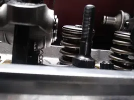
Yes, you can TEMPORARILy run non hardened pushrods with Guideplates, but IMO do not RUN the Motor, only rotate the motor by hand. Can pull the Guideplates & run hardened Washers temporarily & use your other Pushrods...
ANY excess heat or Guideplates rubbing is not in the best interest of any Motor..
Ive set up quite a few of these, found one good illustrated Video that’s correct, there’s SO many ridiculous ones, lol (maybe it’s how I interpret them, IDK.)
incorrect.This is easy to follow, utilizing the 1/2 lift principle).
Check out this one, it’s how I do it, best way to establish geometry in a case such as yours is starting from a simple point, not beginning with seeking Pushrod length, it appears as you run through it. just shows as you move on..
Very easy to get it right ...
Tools you’ll need:
A small tipped permanent sharpie(Black)
A piece ofvKeystock, 8” long. 1/8”-1/2”
Carb cleaner, or Acetone.
A Clean Rag.
Dial Calipers(0–6”). Depth Mic’s if you own.
A Straightedge, I.e. a 2’ long piece of clean 1/4” x 1” flat stock, a long level, aluminum Ruler.
6” steel scale (if you have one).
.PROCESS...
This test will give you the best Pushrod length, once you verify installed Valve Stem height, it’s best to install the Checker Springs to Number1 Cylinder’s Intake and Exhaust Valves.Round off to the closest length.....

OVERVIEW, NOTES TO REFERENCE..

Your CamCard is VERY useful, don’t lose it. All Cam spec’s are listed, and other data can be found using basic Math, and a crucial reference when you’re Degreeing a Cam in.
The OBJECT is to be certain the fine line you Drew on the #1 Cylinder’s Rocker is perpendicular to the Valve Stem sitting in the Head (Meaning the Rocker is at a 90 Degrees angle to the line drawn on the rocker)in relation)
Set the #1 Cylinder at TDC by rotating the motors bolt on the Balancer, make sure it’s on the Combustion stroke (BOTH Valves CLOSED, on the base circle, or “Heel” of the Cam, zero Cam Lift).
Remove ALL the Rockers and Pushrods on the Passenger side engine bank, set them aside.
Lay the straightedge across the tops of the Valve Stems and verify they are all equal in height, measure with a feeler gauge if any gaps are present, higher or lower...list your findings down on your pad. They should all be exactly the same height.Continue with the test, regardless.
Measure the heights of Rocker Studs, if not fully seated Studs can flex and snap, or pull out under threads heavily loaded..
Pull-clean-line and Chase bottom with a Tap or Die Stud with cutting fluid. Threads in Aluminum will be quickly destroyed if not fully seated and torqued, the correct Compound used.
Clean the Rockers surface with Solvent so free of Oil, etc.- so a marker’s lines will stick.
Mark a Dot on the center of the Rocker’s larger pivot Trunnion and center of the Pin that holds the roller Tip in place, dots together,
Place the Rocker-you marked on the #1 Cylinder stud so you can see it well, closest so seen o of the front of the Motor.
Hold the a small straightedge against the line you drew on the Rocker and twist the adjustable Pushrod until the Valve stem sticking up through the Head and the line you drew on the Rocker are exactly 90 degrees apart from one another. Hold a small scale against the Rockers line and verify the two are at 90 Degrees from each other.
Slowly turn the adjustable pushrod so it’s adjusted to 90 degrees, that pushrod length is now the correct length.
LINK BELOW...


View: https://youtu.be/o5is9BsH5OU


Miscellaneous Notes..
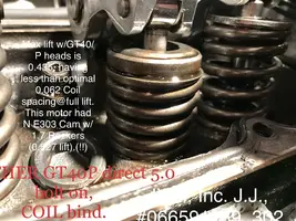
you’ll see Cam LOBE LIFT, and the ROCKER RATIO the Cam is INTENDED TO be USED WITH, E.G.;. 1.6:1, or 1.7:1..ADVERTISED VALVE LIFT IS WHAT NUMBER YOU WANT.,TrickFlow Stage 1 Cam VALVE Lift:.Intake: 0.490, Exhaust: 0.510.
You can also use the LOBE LIFT, and the ROCKER RATIO to find Advertised VALVE lift, simply MULTIPLY. LOBE LIFT/ROCKER RATIO= VALVEVLIFT. 0.510 x 1.6 = 0.3187 (0.319) LOBE LIFT.
Or, you can see what CHANGE in VALVE LIFT you’ll have using a different ROCKER RATIO.
A Cam with an ADVERTISED VALVE LIFT OF 0.550 USING THE CAMCARDS STANDARD FORD Ratio listed as 1.6 can be changed to a 1.7 ROCKER RATIO INCREASES VALVE LIFT, (DURATION is NOT AFFECTED by altering ROCKER Ratio)..
DIVIDE ADVERTISED VALVE LIFT (0.550)
by the CAM Card’s (1.6) RATIO...... 0.550/1.6= 343.7(0.344, which is LOBE LIFT).
Multiply by (1.7)...the new Rocker Ratio, 0.344 x 1.7= 0.5848 (0.585).
OLD Lift=0.550, NEW Lift= 0.585 - 0.550 =.035 VALVE LIFT GAINED by running1.7:1 Ratio Rockers, VS. 1.6:1 Ratio Rockers.The OBJECT is to make sure your line should be perpendicular to your Valve Stem (Meaning 90 Degrees in relation),
Good luck
-John
PS,
RE: Rockers of this Street/mild Strip level..
TrickFlow was the lowest Profile, cut the Studs down/Adjusters & Studmount fits under a Stock Cover on GT40’sbest design IMO. Scorpions are vey good, but Roller tip is massive VS the others, Proforms, (HEARD- NOT SEEN)
LargeTrunnions coming apart on mild Cams, one sucked through the screen &through the pump drive twisted like a pretzel, Ford Comps are good Street Rockers.
Prefer Lunati’s.
 
Yes stock injectors and maf meter.

the one koer code was for left side o2 lean

leakdown test showed no more than 18% in any cylinder (most were below 10%)

block was not decked.

have to check the fuel pressure drop.

unseated spring was an exhaust valve

stock melling oil pump, oe drive

as stated spark plugs electrodes all looked brand new after the few hours of runtime.

no pinging but did backfire in the intake.

straight edge over valve stems shows all valves are pretty close height wise, ( but I will have to check with feeler gauges) same for rocker studs however rocker arm poly locks show significant height differences between intake and exhaust, which I assume is normal in this cam although shouldnt the base circles be the
same ?

the alignment is off towards the outboard side with witness marks that were very favorable ( 0.30)
I will sacrifice the narrower sweep for more centered pattern if can be below 0.70, does that sound reasonable ?