Build Thread Enola- Finishing touches

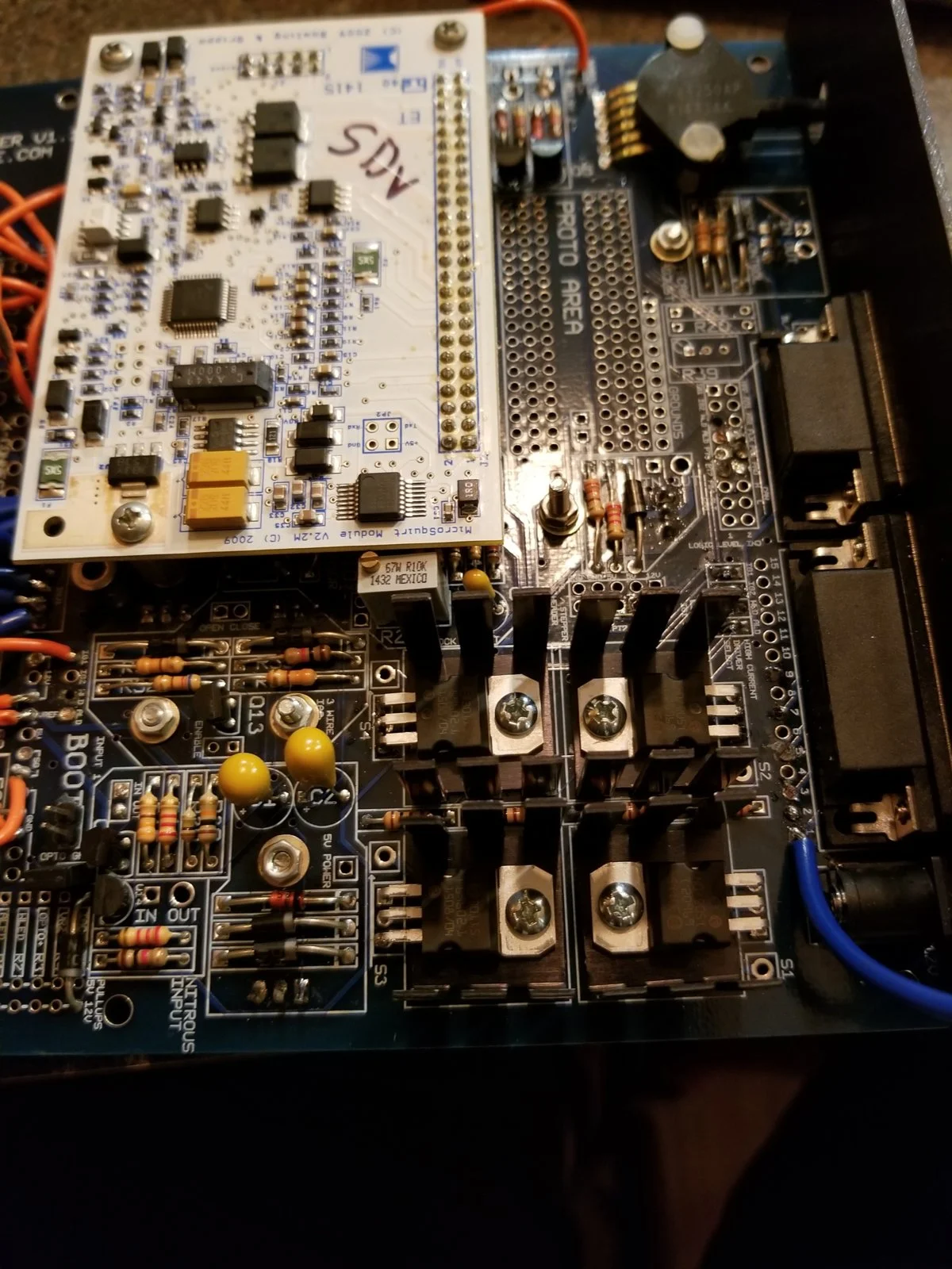
Yesterday I got most of the parts in for my ECU mods, I could not help but go pull it out of the car and start working. The first line of business was to remove any jumpers from the outputs that I need, this didn't take long.
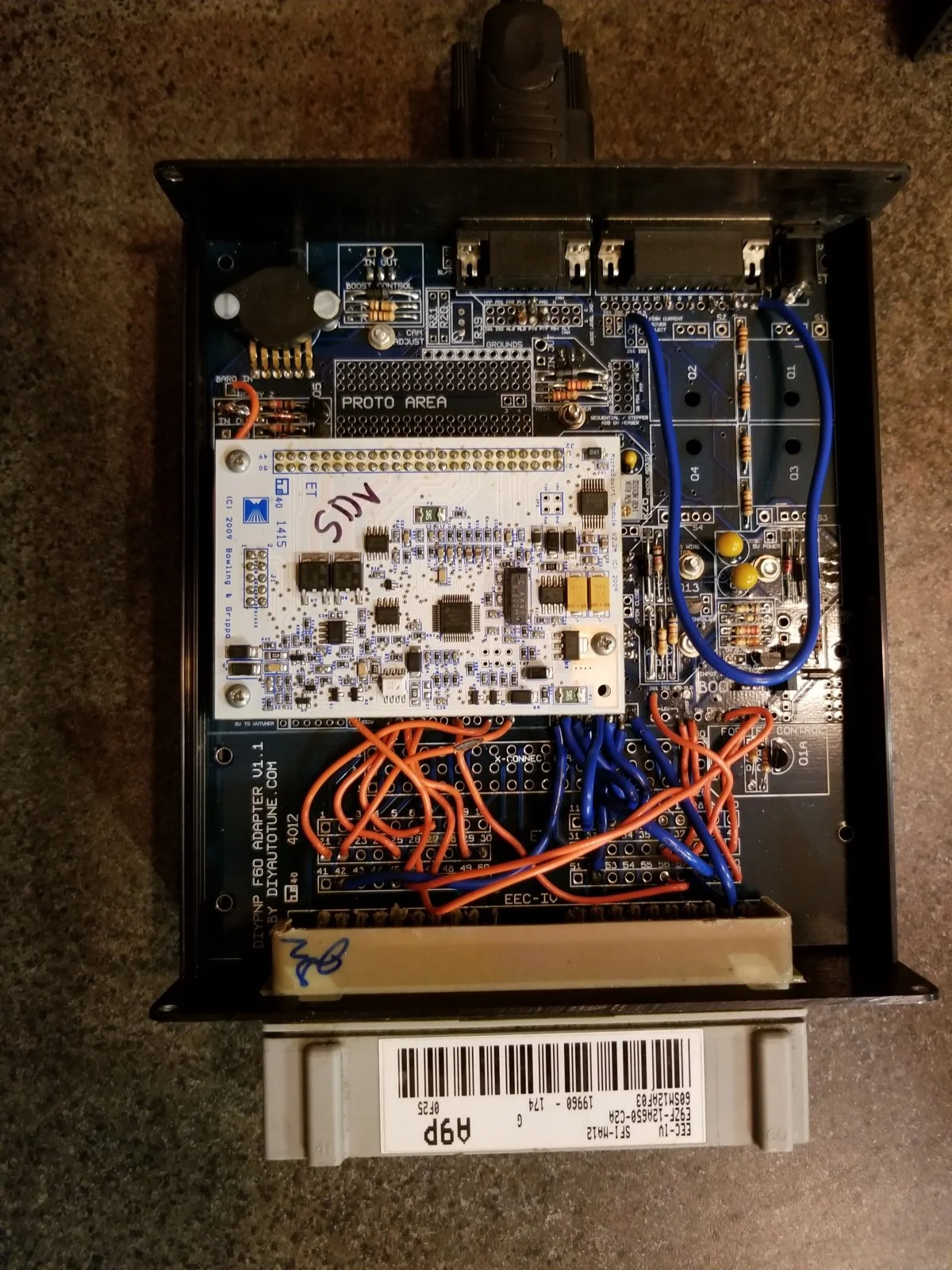
20180419_214317.webp
after beginning to work on it I realized how much nicer it is to have a real electronics soldering iron, when I first built this it was introduction into soldering, I used a massive soldering iron to do the job. Lol I'm surprised I didn't mess up the board.


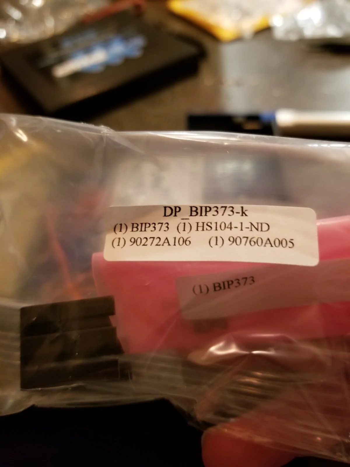
First mod to install were the drivers for direct coil control, these take the 4 logic level ignition outputs (5v) and using a BIP373 transistor circuit convert them to carry the load of driving a coil. The kit I bought for this has large heatsink for them.
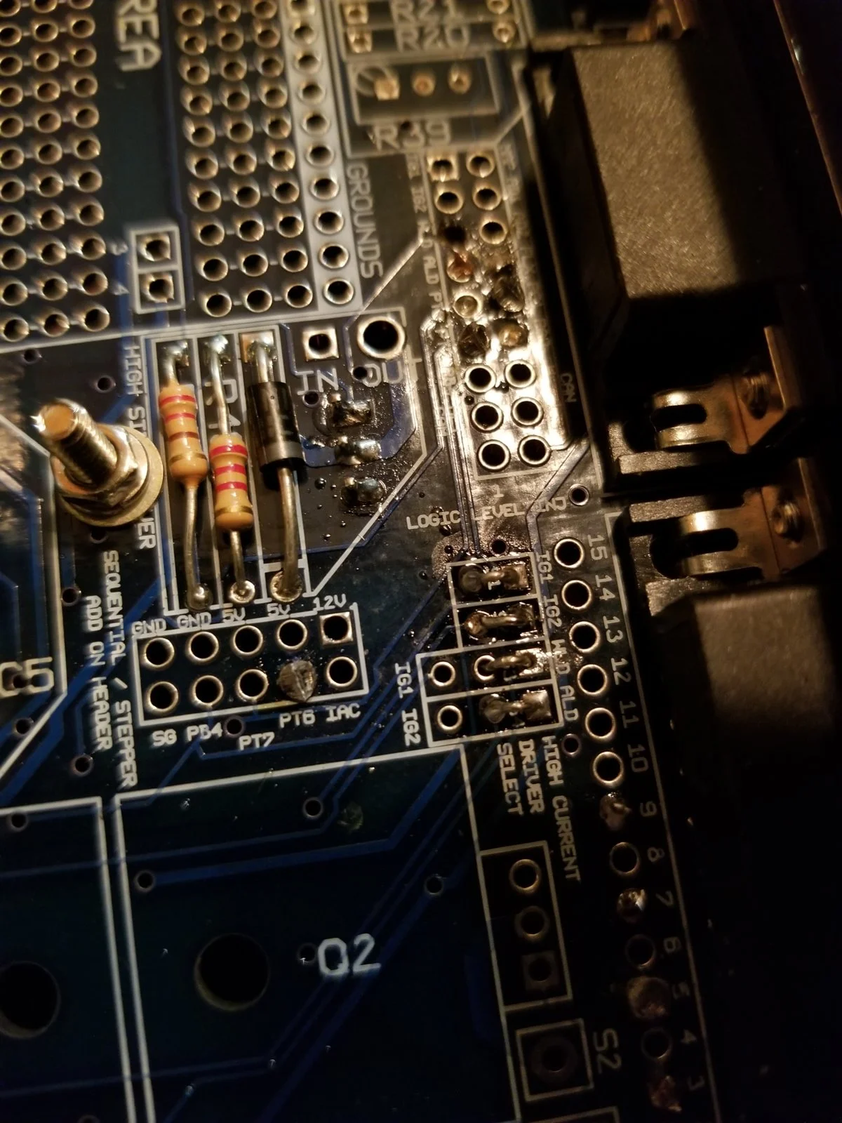
20180419_221046.webp
you can see on the bottom right of the photo I used the clipped legs from resistors as jumpers to tie ign1, ign2, wled, aled to the bip373 circuit to act as drivers. I did not get a picture of it but wled and aled will both need a 5v 100ohm pull up placed in r1 r2 respectively to drive the circuit.
20180419_221522.webp
20180419_222114.webp
20180419_223231.webp
now the mod is installed and ready to be wired to the coils.
 
Yesterday I got most of the parts in for my ECU mods, I could not help but go pull it out of the car and start working. The first line of business was to remove any jumpers from the outputs that I need, this didn't take long.
20180419_214317.webp
after beginning to work on it I realized how much nicer it is to have a real electronics soldering iron, when I first built this it was introduction into soldering, I used a massive soldering iron to do the job. Lol I'm surprised I didn't mess up the board.


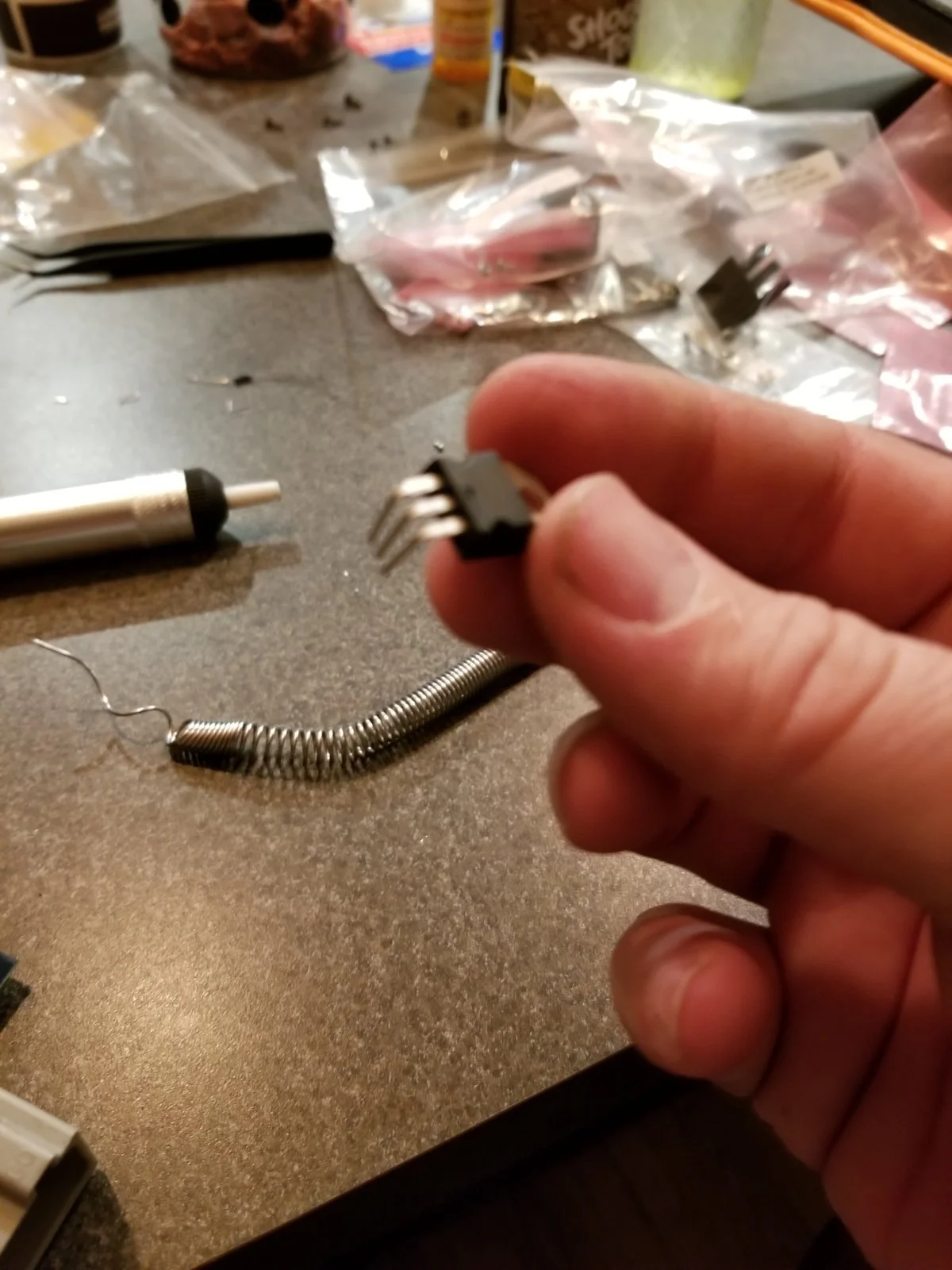
First mod to install were the drivers for direct coil control, these take the 4 logic level ignition outputs (5v) and using a BIP373 transistor circuit convert them to carry the load of driving a coil. The kit I bought for this has large heatsink for them.
20180419_221046.webp
you can see on the bottom right of the photo I used the clipped legs from resistors as jumpers to tie ign1, ign2, wled, aled to the bip373 circuit to act as drivers. I did not get a picture of it but wled and aled will both need a 5v 100ohm pull up placed in r1 r2 respectively to drive the circuit.
20180419_221522.webp
20180419_222114.webp
20180419_223231.webp
now the mod is installed and ready to be wired to the coils.

What coils are you using again with this upgrade...LS coil (COP)?
 
Next up is the semi-sequential injection mod, this one will allow me to run the injectors in a wasted configuration, this will help with tune repeatability and drivability. This mod is simple and uses the center 10pin header next to the proto expansion area.
20180419_223853.webp
20180419_224242.webp
20180419_224255.webp
just like any electronic expansion board the main board gets a header and the expansion gets a header, this allows the board to be removed for service.
20180419_225418.webp
service this area of the board is the breakout area taking io to and from the main board to the 60pin header that plugs into the stock harness.
What a busy area, you can see my original meatball soldering skills even left burn mark on some of the jumpers.... oooppps. That's why they call it learning. I removed the jumpers and pair the injectors up 1,6 3,5 7,4 2,8 these now go to inj1 inj2 inj3 inj4 respectively.
20180419_233413.webp
inj3 inj4 live on this mod board.

I reinstalled the microsquirt board and am now waiting for the tinyio to come in, that will be mounted in the case where I have room.
 
I have an idea, I have plenty of space in the flange on the blower outlet let's say I tap a 1/8npt into each side of this across from each other and use the nozzles that I have. Nitrous solenoids can be PWM controlled so I use one in the line feeding the nozzles, using the boost control output to feed the circuit. The ECU does not know what the circuit is driving and does not care, I can then set the duty cycle tables to reflect how long the solenoid Is open vs boost pressure. This will let me fine tune the spray volume for my application on the fly with a few key strokes.
Thoughts?

You could honestly do it with one nozzle if you have room to get one in there around the middle.

What I can't figure out is why it's so damned hard to find water meth nozzles that look something like this:

1524230701639.webp
 
I know it's very frustrating, the blower outlet is not centered in the plate, not even close. It sits between runners 1,2 5,6 my worry is the back cylinders wont get the extra fuel/cooling effect. I understand the atomized mix will find it's way but I want to err on the side of safety.
20170919_195047.webp
20170919_112559.webp
I'm thinking one nozzle ar the blower outlet and a second next to the bypass valve, this will put one nozzle at each end of the plenum.
 
How about we drill the plate and omit the bar? this will allow me to spray a mist directly into the blower outlet for maximum charge cooling and may be easier to accomplish with what i have. The second nozzle will be for backup, i can make this a smaller nozzle and plumb it with a check valve that takes 16psi to open so no vacuum leak.
20170919_112559 (1)_LI.webp
behold my poor paint skillz!

Red is the nozzle
Blue is a drilled hole
yellow is the feed line
 
I say put little tips in all 8 ports fed by a single solenoid and feed line. That way the spray is dead even across the cylinders.

Only downfall is you won't be able to measure intake plenum temps in the ports....but you can alway read egt.

This is how nitrous is used....so water meth should work, too.
 
So you think spraying into the blower will give me even distribution even though it is at the very front of the plenum area???

I think spraying up toward the discharge port will give the best mix.

If you're spraying in two separate locations in the lower plenum, I don't see how that's going mix evenly given the same quantity sprayed in the face of the discharge port.
 
You mentioned filing your rings in a previous post, I came across an article in my feb 18 street rodder mag that may help you out. It's in the 'shop manual' by Ron Ceridono, a question and answer part of the mag, you may be able to look it up on enthusiastnetwork.com or I can just mail you the mag. The article is called 'rings fit for a king'. Gives you application for turbo/supercharged up to 15psi, top ring, second ring and oil rail figures. Filing techniques and various grinders, you may find it useful.
Or not.
Or just ignore me like mike does, well, he ignores me just most of the time. Can't blame him. I'll stop typing now.
Maybe.
I'll likely just go annoy someone else.
 
You mentioned filing your rings in a previous post, I came across an article in my feb 18 street rodder mag that may help you out. It's in the 'shop manual' by Ron Ceridono, a question and answer part of the mag, you may be able to look it up on enthusiastnetwork.com or I can just mail you the mag. The article is called 'rings fit for a king'. Gives you application for turbo/supercharged up to 15psi, top ring, second ring and oil rail figures. Filing techniques and various grinders, you may find it useful.
Or not.
Or just ignore me like mike does, well, he ignores me just most of the time. Can't blame him. I'll stop typing now.
Maybe.
I'll likely just go annoy someone else.
Thanks JR i will look into it, I am most likely going to follow the guidelines that the ring manufacturer lays out for me. I dont want to ruin a $250 set of gap-less rings.