Build Thread Enola- Finishing touches

Most excellent thank you, few questions sir.
Home ported heads- what if I dont know the flow numbers?
Unsure of valve spring pressures

Will this make a major impact on the cam design? Very much looking forward to working with you, I have heard good things from our members. Also this is a custom blower setup what's the best way to get this information to you?
 
Most excellent thank you, few questions sir.
Home ported heads- what if I dont know the flow numbers?
Unsure of valve spring pressures

Will this make a major impact on the cam design? Very much looking forward to working with you, I have heard good things from our members. Also this is a custom blower setup what's the best way to get this information to you?

Seriously... PUt it all on the form. Everything that you know and every question you have.
 
I will do the write-up after i get the final pictures and do a few output tests with an led to make sure they are working like i want them to. I cant believe it all fit inside the stock case...

Now the VSS sensor I think i am going to tie this into the ecu to get a speed input. Setting myself up for the dash display.
 
  • Like
Reactions: stanglx2002
If
I will do the write-up after i get the final pictures and do a few output tests with an led to make sure they are working like i want them to. I cant believe it all fit inside the stock case...

Now the VSS sensor I think i am going to tie this into the ecu to get a speed input. Setting myself up for the dash display.
you’d think during all this soldering, and updating, you’d take a minute to reply to your pm.:uzi:
 
I will do the write-up after i get the final pictures and do a few output tests with an led to make sure they are working like i want them to. I cant believe it all fit inside the stock case...

Now the VSS sensor I think i am going to tie this into the ecu to get a speed input. Setting myself up for the dash display.

What kind of dash display are you thinking?
 
What kind of dash display are you thinking?
Basically i am going to rip your idea off 100% :D
but i must cross the first hurdle..... figuring out how to build a hall effect conditioning circuit for the VSS input. I am not using the stock speed sensor so this is a must for now. I am also going to build a few ADC conditioning circuits so i can datalog fuel pressure, oil temp, ambient air temp ect....
 
Basically i am going to rip your idea off 100% :D
but i must cross the first hurdle..... figuring out how to build a hall effect conditioning circuit for the VSS input. I am not using the stock speed sensor so this is a must for now. I am also going to build a few ADC conditioning circuits so i can datalog fuel pressure, oil temp, ambient air temp ect....

Glad to be of help :) Need to get back to working on it again. Didn't like the power supply that I got as it doesn't do exactly what I want in shutting down the RPi and the power supply itself.

Are you going to explain the reasons for the computer upgrades as I am trying to understand what you are trying to accomplish? Also, have you looked at the MS3 daughter board as I was looking at it, but I dont understand it enough to see if its worth the money?
 
I would have just gone ms3 if it were an option for me, for the money it is a no brainer upgrade. The software update alone is incredible so much more flexibility. The updates I am doing will give me semi sequential injection for smoother idle and I can control the injection timing events. Along with ECU based ignition control, I am directly controlling the coils no more edis module, this will give me a true spark cut rev limiter and feedback. The tinyIOx is a separate module that works over canbus it allows me to expand the io to work all of my programmable io and allows me to add extra pwm io along with plenty of adc inputs for adding sensors. I used 4 of my outputs for the fuel and ignition mods so this was a must. All together this cost me $120 to do. My unit is basically a microsquirt so I am limited on upgrades.
 
Basically i am going to rip your idea off 100% :D
but i must cross the first hurdle..... figuring out how to build a hall effect conditioning circuit for the VSS input. I am not using the stock speed sensor so this is a must for now. I am also going to build a few ADC conditioning circuits so i can datalog fuel pressure, oil temp, ambient air temp ect....
Do the words Schmitt trigger have any meaning to you? Or are you looking for something other than to trigger on a rising or falling edge?


https://www.google.com/search?biw=1.......0...1.1.64.psy-ab..0.0.0....0.v_lEvRycPT4
 
That's a bit more involved than I need really. I found what I need, I can build it with..
1-10k resistor
1-10 nanofarad capacitor (this will determine the frequency range)
1- bat54 (or two IN4001 diodes)
I may also need a 2.2k resistor fpr the pull-up voltage this is TBD not sure if the sending unit has an internal pull-up
 
I have the entire top end off the old engine not what I expected to see. The cylinders with low compression have wet piston tops with oil. The valves are not wet and the head gaskets were in perfect shape. That leaves just the rings. Once it is out of the car and I can pull the bottom end apart I will know more.
 
WHOOO! that was sorta difficult. I just got done doing the setup on the TinyIOx, who knew the can bus options would be so simple? i was wayyy over thinking things at first. The hardware mods write-up will have to wait for another day as it takes forever to do that from a phone, so i will walk you thru how i did the setup on the expansion card [TinyIOx]..
First you need a few files from this site.
http://forum.jbperf.com/viewtopic.php?f=2&t=1282#p8356
The full detailed instructions on how to use the port scanner are within. I will say this little program makes it very easy to update firmware and you can also change the CAN ID on any device that the port scanner can see. All your CAN devices will show up in the port scanner. BTW you have to have TS closed for this to work.
Step 1: use the link and follow the instructions, the newest firmware version is v2.0
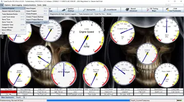
Step 2: now that the TinyIOx has its firmware installed and the CAN ID set [i used ID #4 default] we can move on to setting things up in Tuner studio. First we have to go in to our project properties and setup the TinyIOx make sure to give it a name you can easily identify it by I used TinyIO
?hash=4e0c8e2c52603662336071fb52b7e8af.webp
Can device settings.webp
You have to add the device to the list under [CAN Devices] it will automatically find a device you have connected, then name the device. Under Device Configuration File you need to hit the box with the three little dots, then select the same .ini file you used when burning the firmware they are in the same folder.
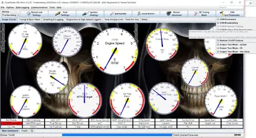
Step 3: Now we are connected you will see a box under the header bar that will allow you to switch between the MS and the TinyIOx but first we need to set the CAN parameters.
?hash=4e0c8e2c52603662336071fb52b7e8af.webp
Can Parameters.webp
These settings are important I will be using generic output IO and a few ADC inputs The CAN ID needs to match your TinyIOx the tables are all found in "7" and the offsets will vary depending on the io type. in this photo i do not have the ADC enabled but the ADC offset needs to be 76.
To use the outputs as a PWM we need to change some of the settings, on the right we can see where it says ":Remote port type" then there are 3 ports each port can be configured differently. When set to [Digital (8 signals)] that one port can support up to 8 digital switches, so you can fire 8 outputs from one port. I plan to use the boost control circuit as a PWM control for my water methonal system using a nitrous solenoid, here is how i would set that up. First i have to set Port 2 to single value [one signal] then go into the boost control settings and use port 2.
Port 2 settings.webp
 

Attachments

  • Project properties.webp
    Project properties.webp
    128.3 KB · Views: 203
  • Can options.webp
    Can options.webp
    124.2 KB · Views: 194
  • Like
Reactions: 90sickfox