CAMTWO1070
Active Member
After reading your initial post Im gonna say one of the many contributing factrs I see & one of the issue could be in the fuel injectors most likely because when you change the duty cycle in them by boosting fuel pressure sky high and go above the recommended pressure settings you overheat them plus another thing to note also does bad things to the computer when the info defies logic and the computer is going crazy trying to compensate for all the mix-match in the tune.............
Do an ohms test on them....You should get 14.4 ohms on a good injector or buy a cheap injector tester...
What most dont know is theres two open spots on the sides of the injector at the sides of the plug where you can put multimeter probes on while the engine is running...

A noid light or noid light set works great too at determining if the ECU has a good signal going to each still too as it will indicate a faulty ECU in need of repair...


You say the pressure wont to to 60 anymore and as you also know the regulator should be set to 39psi with vacuum hose unplugged as this is where the ECU knows how to make its fueling adaptations and corrections ,,,,,,,,,,
You say after all your tinkering you now have 38 and thats ok & where the fuel pressure for the injectors needs to be..,
When you go past the 43.5psi on stock Ford injectors you do bad things to them similar to overheating an engine...

If you have bigger injectors where you need more pressure than your duty cycle changes drastically and without a chip you cant adjust those factors so the computer will go squirrelly and start going into hysteresis........;- especially the air going through the throttlebody setting thats set to 0.550lbs/min in an A9L by the factory..............

After you adjust your fuel pressure and timing without spout connector and set the idle to factory settings unless you have a chip the MAF transfer functions need to be added correctly so the computer can deliver the right air , fuel and spark into the engine using the information the MASS Airflow Meter tells the ECU its handling but thats just a very general overview as theres lots of other settings that need to be adjusted especially when you adjust your idle from the factory setting using the throttlestop screw and the logic within the ECU settings fights whats demanded and is forced to tell lies to the ECU based off of poor information.......................

All of it controls air and fuel to spark and cant correct correctly if not in the ballpark..thats why logfiles are important when you do changes such as yours....
If I was datalogging and using a wideband in conjuntion and the wideband showed that I was in the 16-17:1 range I would increase lbs/min for the first 10 cells from the bottom upby the amount of fuel needed so if I needed 3% more fuel to stabilize a 14.67 stoich then I would increase the botton numbers 3% more..
The throttlestop setting also affects the TPS also the TPS voltage setting and how its read by the ECU too and can become the boy who cried wolf one too many times to an ECU by giving false info...........to calculate MAF flow the TPS must be set between .095-.096 volts and it says it right in the flow calculation parameters too unless you manipulate initial TPS setting aswell as ratch numbers.............
If your tune is say 15% off the logic & at full learn can only correct by 12% up or down because that is how its set in the tune and without a way to fix the tune and increase also decrease the learning rate nothing sensed by the ECU will be honest or become true as all the ECU does is tabulate the settings that makes up the tune and uses whats called a checksum number to run the program that it always reverts to when the kamrf is reset and like I also stated can only adjust 12% up or down..


The only way to change the checksum is with a Ford machine or a chip but most choose the incorrect way by bumping the timing and increasing fuel pressure..
This $3500.00 doodad they now sell on ebay for maybe $300.00 that used to be a Ford Techs extensive weapon against the EEC-IV at exclusive dealerships who chose to purchase them can change the tune settings inside the ECU with zero chip needed............
These days its better and more cost effective buying this than trying to fund a chip and someone who will fearlessly tune it....
.jpg")
.jpg")
This is a logfile shot of my newest project where I was tabulating MAF airflow so I had the ISC locked out with all of the flow going through the TB alone....................

With the ISC combined the actual number drops to around 1.2 lbs/min and before the settings change my headders were glowing at idle.........LOL
Sounds like youre not using the fuelpump monitor (wire#19) by hardwiring the fuelpump from the battery through a relay & using the pink wire as a trigger wire and not using the pink wire off the relay melded with wire #19 to run the fuel pump which actually fluxuates voltage to spin the pump faster and slower to compensate in highs and lows in the driving aswell as battery voltage...,,Its all in the tune....voltage plays a key role in it...........

Usually when you need to crank up the pressure as high as 60psi you need to step-up the fuelpump flow to atleast a 255lph/hr flow and have injectors capable of being set that high then the injector information must be changed in the ECU........
Heres some info to process....On a stock 19lb/hr injector the high slope is 19lbs and the low slope is 26lbs and the fuel pressure is set at 39 without a vacuum signal..With a vacuum signal it drops to around 33psi then increases to 39psi..........33-39psi is already quite a signifigant number increase over the lowslope number and also to note is also how you control fuel rate....
If I want more fuel but a lesser duty cycle by say 3% I would increase the lowslope number by 3% so it works less harder..............

Another area to check is the #4 wire coming off the ECU that goes to pin #5 on the TFI plug....Make sure it has 22kohms of resistance..
If it doesnt show atleast 22kohms and youre running the push start non CCD TFI module used by the A9L youll feed raw unfiltered power into the PIP signal causing all sorts of internal noise the ECU cant tune out............

Another thing I want to touch upon is the clutch switch or the neutral safety switch which is this lil area right here....

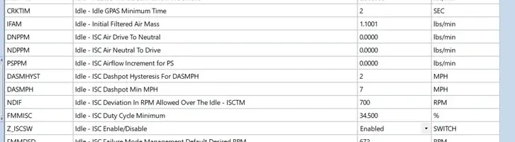
Most bypass the switch by twisting the wires together or leave them open and thats bad and heres why............See these settings in the tune?

After you bypass the clutch switch the TRLOAD should be switched to 0 which is a forced neutral state then the "special injector fuel table at idle" and "special injector fuel table in neutral" settings must be enabled...

They affect these settings plus a whole lot more....................If you dont want them to be a contributing factor you must change the trans settings..

I had my clutch switch wires twisted together and it affected the way my vehicle idles after driving it for 35-40 mins and found out that the ECU was having quite a time trying to make sense why the vehicle was displaying speed when the clutch was always depressed so instead of making 12 changes in the tune I hooked the clutch switch back up...
The worst that became the contributing factor in it was when it was first fired up and ran great until 15-20 mins into the drive because the adaptive learning was trying to adjust for my driving thinking it was sitting in neutral and after 35-40 mins a different table took over and created the high idle syndrome.....................LOL
Good Luck
Do an ohms test on them....You should get 14.4 ohms on a good injector or buy a cheap injector tester...
What most dont know is theres two open spots on the sides of the injector at the sides of the plug where you can put multimeter probes on while the engine is running...
A noid light or noid light set works great too at determining if the ECU has a good signal going to each still too as it will indicate a faulty ECU in need of repair...
You say the pressure wont to to 60 anymore and as you also know the regulator should be set to 39psi with vacuum hose unplugged as this is where the ECU knows how to make its fueling adaptations and corrections ,,,,,,,,,,
You say after all your tinkering you now have 38 and thats ok & where the fuel pressure for the injectors needs to be..,
When you go past the 43.5psi on stock Ford injectors you do bad things to them similar to overheating an engine...
If you have bigger injectors where you need more pressure than your duty cycle changes drastically and without a chip you cant adjust those factors so the computer will go squirrelly and start going into hysteresis........;- especially the air going through the throttlebody setting thats set to 0.550lbs/min in an A9L by the factory..............
After you adjust your fuel pressure and timing without spout connector and set the idle to factory settings unless you have a chip the MAF transfer functions need to be added correctly so the computer can deliver the right air , fuel and spark into the engine using the information the MASS Airflow Meter tells the ECU its handling but thats just a very general overview as theres lots of other settings that need to be adjusted especially when you adjust your idle from the factory setting using the throttlestop screw and the logic within the ECU settings fights whats demanded and is forced to tell lies to the ECU based off of poor information.......................
All of it controls air and fuel to spark and cant correct correctly if not in the ballpark..thats why logfiles are important when you do changes such as yours....
If I was datalogging and using a wideband in conjuntion and the wideband showed that I was in the 16-17:1 range I would increase lbs/min for the first 10 cells from the bottom upby the amount of fuel needed so if I needed 3% more fuel to stabilize a 14.67 stoich then I would increase the botton numbers 3% more..
The throttlestop setting also affects the TPS also the TPS voltage setting and how its read by the ECU too and can become the boy who cried wolf one too many times to an ECU by giving false info...........to calculate MAF flow the TPS must be set between .095-.096 volts and it says it right in the flow calculation parameters too unless you manipulate initial TPS setting aswell as ratch numbers.............
If your tune is say 15% off the logic & at full learn can only correct by 12% up or down because that is how its set in the tune and without a way to fix the tune and increase also decrease the learning rate nothing sensed by the ECU will be honest or become true as all the ECU does is tabulate the settings that makes up the tune and uses whats called a checksum number to run the program that it always reverts to when the kamrf is reset and like I also stated can only adjust 12% up or down..
The only way to change the checksum is with a Ford machine or a chip but most choose the incorrect way by bumping the timing and increasing fuel pressure..
This $3500.00 doodad they now sell on ebay for maybe $300.00 that used to be a Ford Techs extensive weapon against the EEC-IV at exclusive dealerships who chose to purchase them can change the tune settings inside the ECU with zero chip needed............
These days its better and more cost effective buying this than trying to fund a chip and someone who will fearlessly tune it....
This is a logfile shot of my newest project where I was tabulating MAF airflow so I had the ISC locked out with all of the flow going through the TB alone....................
With the ISC combined the actual number drops to around 1.2 lbs/min and before the settings change my headders were glowing at idle.........LOL
Sounds like youre not using the fuelpump monitor (wire#19) by hardwiring the fuelpump from the battery through a relay & using the pink wire as a trigger wire and not using the pink wire off the relay melded with wire #19 to run the fuel pump which actually fluxuates voltage to spin the pump faster and slower to compensate in highs and lows in the driving aswell as battery voltage...,,Its all in the tune....voltage plays a key role in it...........
Usually when you need to crank up the pressure as high as 60psi you need to step-up the fuelpump flow to atleast a 255lph/hr flow and have injectors capable of being set that high then the injector information must be changed in the ECU........
Heres some info to process....On a stock 19lb/hr injector the high slope is 19lbs and the low slope is 26lbs and the fuel pressure is set at 39 without a vacuum signal..With a vacuum signal it drops to around 33psi then increases to 39psi..........33-39psi is already quite a signifigant number increase over the lowslope number and also to note is also how you control fuel rate....
If I want more fuel but a lesser duty cycle by say 3% I would increase the lowslope number by 3% so it works less harder..............
Another area to check is the #4 wire coming off the ECU that goes to pin #5 on the TFI plug....Make sure it has 22kohms of resistance..
If it doesnt show atleast 22kohms and youre running the push start non CCD TFI module used by the A9L youll feed raw unfiltered power into the PIP signal causing all sorts of internal noise the ECU cant tune out............
Another thing I want to touch upon is the clutch switch or the neutral safety switch which is this lil area right here....
Most bypass the switch by twisting the wires together or leave them open and thats bad and heres why............See these settings in the tune?
After you bypass the clutch switch the TRLOAD should be switched to 0 which is a forced neutral state then the "special injector fuel table at idle" and "special injector fuel table in neutral" settings must be enabled...
They affect these settings plus a whole lot more....................If you dont want them to be a contributing factor you must change the trans settings..
I had my clutch switch wires twisted together and it affected the way my vehicle idles after driving it for 35-40 mins and found out that the ECU was having quite a time trying to make sense why the vehicle was displaying speed when the clutch was always depressed so instead of making 12 changes in the tune I hooked the clutch switch back up...
The worst that became the contributing factor in it was when it was first fired up and ran great until 15-20 mins into the drive because the adaptive learning was trying to adjust for my driving thinking it was sitting in neutral and after 35-40 mins a different table took over and created the high idle syndrome.....................LOL
Good Luck
Attachments

Last edited: