Digital Tuning Innovate LC-1 users in here (long)

trinity_gt

10 Year Member
Jan 31, 2003
3,125
80
99
Canada
I installed an Innovate LC-1 in my KB 02 GT last summer and have two issues I'd like to pass by others for feedback.

Background: The car is running the factory H-pipe. I have removed the B2S1 O2 sensor and installed the WB sensor there. I wired the LC-1's Analog 1 output to the factory O2 sensor wiring at the top of the bellhousing and am using it as a narrow-band simulator. Analog 2 feeds my A-pillar mounted WB gauge. I'm confident the wiring is correct and sound but am open to all suggestions...

Issue 1: Engine-start procedure or gauge doesn't register
If I get into the car I basically need to turn the ignition on but not start the engine and wait for the gauge needle to make a complete sweep (0 to 18 and back to 0). If I start the car then everything seems to work fine. If I start the car while the sweep is in progress, however, the needle will subsequently sit at 0 and not move. If I turn the ignition off, wait a second, and then do the procedure "right" the gauge behaves normally again.

Anyone else seen this?

Issue 2: B2S1 OBD codes
If I allow the engine to idle for a while -- say, a minute or two -- sometimes the SES light comes on. When I pull the codes I get P0174 (system too lean B2) and P1151 (lack of O2 sensor switches on B2S1, bank lean.) This is the input to which I have the LC-1 connected. I hooked up my scanner and took a few screen shots while idling and running it up to 2000RPM.

Here's a "closeup" shot of the front O2 sensors for B1 (green) and B2 (blue). This is at hot idle:
hotidle13sec.jpg


Here's a shot while holding the engine at 2000RPM in neutral:
2000rpm13sec.jpg


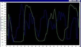
Here's a couple more "zoomed out".

Idle:
hotidle13secwide.jpg


Holding 2K RPM:
2000rpm13secwide.jpg


You can see that at idle the B2 signal seems to be full of noise and random variations. At 2000RPM, however, it looks much better, much more like the "real" O2 sensor (green.)

I've tried programming different time values (instant, 1/12, 1/6 and 1/3-sec) and it doesn't really seem to make a difference to the signal quality.

I can't see this being a wiring problem since I wouldn't think that would be RPM sensitive. As well, the WB gauge on the pillar doesn't do anything unexpected. For example, I see no evidence B2 is "lean". At idle the gauge is ~14.5:1 (give or take). It's not like it's constantly above 15:1 or more.

Any ideas on this? Anyone else using this analog output in this fashion? Is this perhaps a firmware revision issue?
 

Attachments

  • hotidle13sec.jpg
    hotidle13sec.jpg
    62 KB · Views: 125
  • hotidle13sec.jpg
    hotidle13sec.jpg
    62 KB · Views: 109
  • 2000rpm13sec.jpg
    2000rpm13sec.jpg
    81.8 KB · Views: 85
  • 2000rpm13sec.jpg
    2000rpm13sec.jpg
    81.8 KB · Views: 86
  • hotidle13secwide.jpg
    hotidle13secwide.jpg
    85.6 KB · Views: 94
  • hotidle13secwide.jpg
    hotidle13secwide.jpg
    85.6 KB · Views: 118
  • 2000rpm13secwide.jpg
    2000rpm13secwide.jpg
    113.2 KB · Views: 100
  • 2000rpm13secwide.jpg
    2000rpm13secwide.jpg
    113.2 KB · Views: 87
  • Sponsors (?)


Heya Trinity...

What you are seeing there is the delay between when the EEC wants to reference the Narrow band 02 sensor and when the LC-1 wants to start simulating the signal.

That wideband Bosch sensor isn't going to start doing ANYTHING until the sensor gets up to temperature. The LC-1 knows that. It will wait until the sensor is warmed up to 80% (ish) before it does anything with it at all.

I run the LM-1. Have for years. Initially, I replaced a narrow band sensor with the wide and ran the signal wire. Similar buggery to what you're seeing. The only difference is that the LM-1 reports on the display, what's going on with the status of heating the wideband (don't think the LC-1 does).

To my knowledge, you have two options:

Put the narrow sensor back in and install another bung for the wideband
Wait the time that it takes for the wide band sensor to reach 80% of op temp (about the time it takes for a needle sweep it sound like) before starting the car.

I went with the former. It was just too simple to stop by a muffler shop and have them install a bung.

Computerized Engine Controls said:
By Steve V. Hatch

Oxygen Sensor

Initially, the oxygen sensor was a single-wire sensor. In later model years, multi-wire sensors are used, both to provide an independant ground circuit for the signal and to provide high current power and ground circuits for an electrical heater to get the sensor up to operating temperature more quickly.

The TBI and PFI systems use a PCM-generated 450 mV signal, known as a bias voltage, whi it places on the oxygen sensor signal wire. The PCM places this bias voltage on the oxygen sensor signal wire whenever the engine is started and until the O2S begins to generate its own voltage. The PCM's voltage-sensing circuits continue to watch this voltage signal. As the engine is warming up, eventually the voltage begins to exceed the 450 mV bias voltage placed on this circuit by the PCM, at which point the PCM knows that the O2S is hot enough to begin generating its own voltage; the PCM will then remove the bias voltage signal and watch the voltage that the O2S is placing on the circuit. Therefore, when watching the O2S voltage values with a scan tool immediately after a cold engine start, expect to see a value of 450 mV, even before the oxygen sensor is hot enough to operate.
 
Heya Trinity...

Hey Noobz. Thanks for the reply.

What you are seeing there is the delay between when the EEC wants to reference the Narrow band 02 sensor and when the LC-1 wants to start simulating the signal.

That wideband Bosch sensor isn't going to start doing ANYTHING until the sensor gets up to temperature. The LC-1 knows that. It will wait until the sensor is warmed up to 80% (ish) before it does anything with it at all.

I run the LM-1. Have for years. Initially, I replaced a narrow band sensor with the wide and ran the signal wire. Similar buggery to what you're seeing. The only difference is that the LM-1 reports on the display, what's going on with the status of heating the wideband (don't think the LC-1 does).

To my knowledge, you have two options:

Put the narrow sensor back in and install another bung for the wideband
Wait the time that it takes for the wide band sensor to reach 80% of op temp (about the time it takes for a needle sweep it sound like) before starting the car.

I went with the former. It was just too simple to stop by a muffler shop and have them install a bung.

For issue 1, I don't mind waiting for the full sweep of the G2 gauge at start though I don't think its behavior is being caused by the sensor not being warmed. It's like the electronics in the gauge get screwed if switched-power is cut whilst in the sweep. Is it even supposed to sweep like that? Maybe I've got the power connected to the wrong points...

But for issue 2, you've piqued my curiosity re sensor temperatures, specifically at idle. The scan tool is showing what is almost nonsense coming out of the LC-1 at idle but at 2000RPM it looks fine. A sensor that is too cool might do this. Thing is the LC-1 should have closed-loop control of the heater in the Bosch sensor so even at idle it should be staying warm enough. My daily is a 2002 VW GTI and it uses the same Bosch WB sensor as original equipment) and it has no issues at idle.

I have thought about the 2nd bung. I don't know if there's room for a 2nd bung in the factory pipe between the manifold and the first cat but I do have an MRT catted H-pipe I took of a couple of years ago because I was having emissions problems with it. I had a bung installed in that for WB dyno sessions. I might put that pipe on, put the OE sensor in the top bung and the WB in the 2nd on and run like that.

But I'm still troubled by the WB setup giving a wonky analog output at idle.
 
I couldn't tell you whether the sweep is normal operation or not for your gauge. I've seen others do something similar but again, I don't have the same system you do.

Nearly all of my response was directed toward your second problem with small caveat that part of your symptom in problem one was interrelated. That is, if you turn the ignition "on" and wait say.... 20 seconds for starters... Once that sensor is warmed up, things should act fairly normal.

It's not that the PCM doesn't know that it's in open or closed loop. It's that the PCM does take a reference shot at the sensors on startup. That reference is completely different between actual and the simulated signal (or lack thereof) that it's getting from the LC-1.

Once warmed up and happy though... They seem to a pretty damned good job of simulating that narrow band.
 
Oh... and your idle waveform? I wouldn't worry about it too much. If I remember, an actual O2 sensor switches a lot faster than the simulated one (or vise-versa... I don't actually recall).
 
I don't have to wait 20-seconds. I wait only for a full gauge sweep to complete -- maybe 1-2 seconds -- and then start it. If I fail to wait for the sweep to finish the gauge just sits as '0' but the LC-1 appears to work fine.

The idle waveform shown above in blue is not normal. It's why I'm getting the codes I am. The charts show the passenger side front O2 (green) and the LC-1 simulated output (blue.) At 2000RPM the waveforms are nearly identical -- as expected -- but the LC-1 output at idle is really nothing like the factory O2 which is shown to be operating exactly as expected. The LC-1 output looks like it's just jittering and noisy.

Since this only happens at idle I'm thinking it's not wiring or connections. I'm leaning toward sensor temperature or some sort of firmware or hardware fault in the LC-1. Sensor temp seems unlikely since it's in the factory location in the factory H-pipe: Very close to the manifold in heavy-gauge pipe.

Very mysterious. This is why I was hoping to hear from others with this setup.
 
Sensor temp seems unlikely since it's in the factory location in the factory H-pipe: Very close to the manifold in heavy-gauge pipe.

Think about this for a second then reread the quote in my initial post.

When the OEM sensor is referenced, it's basically referenced for its existence and that it's not shorted. The bias voltage is what is referenced. The PCM takes a look at it and is looking for a predictable response. The response it's getting from the simulated narrowband sensor is gibberish to the PCM.

As far as the waveform goes, the "noise" is really inconsequential. The expected response to the PCM is stoich, out of range high, and out of range low. Despite how "noisy" the waveform appears, the only thing the PCM is looking at is the peaks and valleys. Though the blue waveform has a lot more chop in it, the high and lows pretty much mirror your OEM sensor. The only reason it looks like it does is because there's more time between cycles at idle than there is at 2k rpm.

The only reason I mention your gauge sweep [at all] is because of the time delay. No other reason. The time that it takes for sweep (whether 2 seconds or 60) appears to be the time necessary for things on the end of the simulated sensor, to get in line with what the PCM expects to see during reference.

4 wire heated sensors are a wonderful thing. Some parts of it get dicey when their use differs from whatever OEM is.

Good luck with it. :nice: