New 130 amp not charging? PLEASE HELP ASAP

HORSPWR101

New Member
Jan 16, 2006
4
0
0
ok guys..i just put a new 130 amp alternator with optional wiring harness onto my 92 notch. I also upgraded my battery to a blue top optima battery. my problem is that im getting power to the main lead on the alternator(where the two black/orange wires meet). Everything is wired as is in the directions and everywhere i have read on here for the past three hours..lol..im still getting no charge.. i figure..bad alternator..took and had it tested..charges great on the machine but not my car. Any suggestion on what to check next?

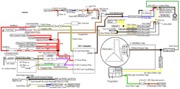
I read on another forum that if the battery light doesnt work on the instrument cluster, that its not getting a signal to the alternator to start charging and it wont kick in? is this true? i did just replace my cluster and am not sure if that light works or not. havent paid much attention due to me not being able to drive it..lol ANyways..PLEASE help me out here guys..need some info ASAP as the summer days are coming and the stang needs to breath..lol..Thanks
 
  • Sponsors (?)


the stator wire being the wire not used from the plug?
the two black and orange wires, the extra wire that has its own plug on the 130 alternator..is that the stator wire? the only two places i have voltage is the two bacl and orange wires, and the first wire from the top side of the voltage regulator plug.
 
If you can not make sense of the diagrams, I may not be much help to you. But here goes...

fuel-alt-links-ign-ac.gif


Note: all voltage measurements use the chassis as the ground. When you make a voltage measurement, it is assumed that one voltmeter lead is connected to ground.

Notice the ignition switch in the lower RH corner of the diagram. It has a red/lt green wire that goes to the alternator warning light. It should have 12 volts when the ignition switch is in the run position. No 12 volts and the ignition switch is bad. This is the signal that tells the regulator to turn on and supply current to the alternator field windings.

Turn the ignition switch off & disconnect the small plug on the alternator. You will find 3 wires: white/black, yellow/white & lt green/red. The yellow/white wire should have 12 volts on it. No 12 volts and the fuse link shown in the diagram is open.

Next make sure the ignition switch is on and measure the voltage on the lt green/red wire. It should be 12 volts. No 12 volts and the wire is broken, or the 500 ohm resistor and dash indicator lamp is bad.

Turn the ignition switch off, and measure the resistance between the lt green wire and the red/lt green wire on the ignition switch. You should see 500 ohms or less. More than the 500 ohms indicates bad wiring or a bad connection.

Next disconnect the plug with the 2 black/orange wires and the white/black wire. Measure the resistance between the white/black wire on the big plug with the black/orange wires and the white/ black wire smaller plug with the lt green/red, yellow/white wires. It should be less than 1 ohm. More than that indicates bad wiring or bad connection in the white/black wire.
 

Attachments

  • fuel-alt-links-ign-ac.gif
    fuel-alt-links-ign-ac.gif
    83.1 KB · Views: 29
That's your problem then. You have 12 on the thick wire and green wire, that's good. They should both have 12 volts constant, meaning even when the ignition is off. The center wire of the 3 wire plug I believe is white. That wire should have 12 volts when you turn the ignition on. That wire is also spliced to go to the small one-wire hookup on the alternator, which is the stator wire. If you don't have 12 volts here, you won't get any output from the alternator.
 
jerryD said:
this might be easier to decipher:

99a89284.gif
Great drawing, except for using the black/orange wires. They definitely need to be replaced with a 4 gauge wire & fuse.
 

Attachments

  • 99a89284.gif
    99a89284.gif
    77 KB · Views: 35
guys thanks a million..found my problem last night..i swapped clusters from a 88 in my 92...re swapped my clusters this morning and everything is like new..charging perfect etc..thanks
 
jrichker said:
Great drawing, except for usuing the black/orange wires. They definitely need to be replaced with a 4 gauge wire & fuse.


Please heed this warning. This was the topic of much theoretical debate on this forum a many moons ago. Well it hasn't even been a full month since I watched an 85 practically burn itself up at the quickie mart just down the street. All fusible links and the black and orange wires went up in smoke due to what appeared to be an internal problem with a 160 amp alt. Owner tells me it had been installed like that for more than year with "No Probems". Wish I had a dollar for every time I heard THAT on this forum. I would really liked to have had the time to take pics of the carnage and troubleshoot it down to the exact cause.
 
i didn't make the pic, just got it from some other board. if you know how or want to take the time to photochop it and add the 4awg wire you may. repost it and i'll start using that pic. is it still gonna harm anything if the two black/orange wires are still used along with the 4awg wire?


jrichker said:
Great drawing, except for using the black/orange wires. They definitely need to be replaced with a 4 gauge wire & fuse.
 
Yes it will, because if something should happen causing the fuse in the 4g wire to blow, now you're still connected by only the small factory wires and you have whatever problem caused the main fuse to blow. This equals a risk high enough that you're almost guaranteed things burning up.
 
I also dont agree with the [several-many] articles that have one run the new cable in parallel to the oem cable. The stock cable doesnt effectively add anything, so I have no clue why anyone would consider using it.

The issue seems to lie in wondering if the stock circuit protection will blow before the rest of the existing wire [or the links themselves] catch on fire. It's kinda' ironic.

Good luck.