Weak spark is most likely low voltage at the ignition coil or a bad TFI. Look for 12 volts at the coil red/green wire with the ignition switch in the Run position. No good12 volts and the fuse link for the ignition system or ignition switch is bad.
Code 51 Engine Coolant Temperature (ECT) sensor signal is/was too high -
Possible bad ECT sensor, or wiring. Possible missing signal ground –
black/wire wire broken or bad connection. With the power off, measure the
resistance between the black/white wire and battery ground. You should see
less than 1 ohm. Check the same black /white wire on the TPS and MAP
sensor. More than 1 ohm there and the wire is probably broken in the harness
between the engine and the computer. The 10 pin connectors pass the
black/white wire back to the computer, and can cause problems.
The ECT sensor is not the same as the temp sender for the temp gauge. It is located in the front part of the tubing that feeds coolant to the heater. It has two wires connected to it.
Pin 7 on the computer - ECT signal in. at 176 degrees F it should be .80 volts
Voltages may be measured across the ECT by probing the connector from the rear.
Use care in doing it so that you don't damage the wiring or connector.
50 degrees F = 3.52 v
68 degrees F = 3.02 v
86 degrees F = 2.62 v
104 degrees F = 2.16 v
122 degrees F = 1.72 v
140 degrees F = 1.35 v
158 degrees F = 1.04 v
176 degrees F = .80 v
194 degrees F = .61
212 degrees F = .47 v
230 degrees F = .36 v
248 degrees F = .28 v
Ohms measures at the computer with the computer disconnected, or at the sensor with the sensor disconnected.
50 degrees F = 58.75 K ohms
68 degrees F = 37.30 K ohms
86 degrees F = 27.27 K ohms
104 degrees F = 16.15 K ohms
122 degrees F = 10.97 K ohms
140 degrees F = 7.60 K ohms
158 degrees F = 5.37 K ohms
176 degrees F = 3.84 K ohms
194 degrees F = 2.80 K ohms
212 degrees F = 2.07 K ohms
230 degrees F = 1.55 K ohms
248 degrees F = 1.18 k ohms
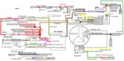
Diagram courtesy of Tmoss & Stang&2birds
See the following website for some help from Tmoss (diagram designer) & Stang&2Birds (website host) for help on 88-95 wiring
Mustang FAQ - Wiring & Engine Info
http://www.veryuseful.com/mustang/tech/engine/images/IgnitionSwitchWiring.gif
http://www.veryuseful.com/mustang/tech/engine/images/fuel-alt-links-ign-ac.gif
http://www.veryuseful.com/mustang/tech/engine/images/88-91_5.0_EEC_Wiring_Diagram.gif
Code 53 - Throttle Position sensor too high – TPS – TPS out of adjustment, bad connections, missing signal ground, bad sensor.
Wire colors & functions:
Orange/white = 5 volt VREF from the computer
Dark Green/lt green = TPS output to computer
Black/white = Signal ground from computer
Always use the Dark green/lt green & Black/white wires to set the TPS base voltage.
Do the test with the ignition switch in the Run position without the engine running.
Use the Orange/white & Black white wires to verify the TPS has the correct 5 volts source from the computer.
Setting the TPS: you'll need a good Digital Voltmeter (DVM) to do the job. Set the TPS voltage at .5- 1.1 range. Because of the variables involved with the tolerances of both computer and DVM, I would shoot for somewhere between .6 and 1.0 volts. Unless you have a Fluke or other high grade DVM, the second digit past the decimal point on cheap DVM’s is probably fantasy. Since the computer zeros out the TPS voltage every time it powers up, playing with the settings isn't an effective aid to performance or drivability. The main purpose of checking the TPS is to make sure it isn't way out of range and causing problems.
The Orange/White wire is the VREF 5 volts from the computer. You use the Dark Green/Lt green wire (TPS signal) and the Black/White wire (TPS ground) to set the TPS. Use a pair of safety pins to probe the TPS connector from the rear of the connector. You may find it a little difficult to make a good connection, but keep trying. Put the safety pins in the Dark Green/Lt green wire and Black/White wire. Make sure the ignition switch is in the Run position but the engine isn't running.
Here’s a TPS tip I got from NoGo50
When you installed the sensor make sure you place it on the peg right and then tighten it down properly. Loosen the back screw a tiny bit so the sensor can pivot and loosen the front screw enough so you can move it just a little in very small increments. I wouldn’t try to adjust it using marks.
(copied from MustangMax, Glendale AZ)
A.) Always adjust the TPS and Idle with the engine at operating temp. Dive it around for a bit if you can and get it nice and warm.
B.) When you probe the leads of the TPS, do not use an engine ground, put the ground probe into the lead of the TPS. You should be connecting both meter probes to the TPS and not one to the TPS and the other to ground.
C.) Always reset the computer whenever you adjust the TPS or clean/change any sensors. I just pull the battery lead for 10 minutes.
D.) The key is to adjust the TPS voltage and reset the computer whenever the idle screw is changed.
The TPS is a variable resistor, must like the volume control knob on a cheap radio. We have all heard them crackle and pop when the volume is adjusted. The TPS sensor has the same problem: wear on the resistor element makes places that create electrical noise. This electrical noise confuses the computer, because it expects to see a smooth increase or decrease as the throttle is opened or closed.
TPS testing: most of the time a failed TPS will set code 23 or 63, but not always. Use either an analog meter or a DVM with an analog bar graph and connect the leads as instructed above. Turn the ignition switch to the Run position, but do not start the engine. Note the voltage with the throttle closed. Slowly open the throttle and watch the voltage increase smoothly, slowly close the throttle and watch the voltage decrease smoothly. If the voltage jumps around and isn’t smooth, the TPS has some worn places in the resistor element. When the throttle is closed, make sure that the voltage is the same as what it was when you started. If it varies more than 10%, the TPS is suspect of being worn in the idle range of its travel.
Adjusting the TPS fails to resolve the problem:
Check the black/white wire resistance. Connect one ohmmeter lead to the black/white wire on the TPS and one lead to the negative post on the battery. You should see less than 1.5 ohm, more than that indicates a problem.
Always take resistance measurements with the circuit powered off.
Clean the 10 pin salt & pepper shaker connectors.
.
See
Registrant WHOIS contact information verification for more help
b]Code 54 – ACT sensor out of range.[/b] Broken or damaged wiring, bad ACT sensor. Note that that if the outside air temp is below 50 degrees F that the test for the ACT can be in error.
Check the resistance of the black/white wire to battery ground. If it is less than 2 ohms, it is good. If it is more than 2 ohms, the black/white wire has bad connections or a broken wire. Always take resistance measurements with the circuit powered off.
Then check the resistance of the ACT sender located in the #5 intake runner on most 5.0 stangs.
ACT & ECT test data:
The ACT & ECT have the same thermistor, so the table values are the same
Pin 7 on the computer - ECT signal in. at 176 degrees F it should be .80 volts
Pin 25 on the computer - ACT signal in. at 50 degrees F it should be 3.5 volts. It is a good number if the ACT is mounted in the inlet airbox. If it is mounted in the lower intake manifold, the voltage readings will be lower because of the heat transfer. Here's the table :
68 degrees F = 3.02 v
86 degrees F = 2.62 v
104 degrees F = 2.16 v
122 degrees F = 1.72 v
140 degrees F = 1.35 v
158 degrees F = 1.04 v
176 degrees F = .80 v
194 degrees F = .61
Ohms measures at the computer with the computer disconnected, or at the sensor with the sensor disconnected.
50 degrees F = 58.75 K ohms
68 degrees F = 37.30 K ohms
86 degrees F = 27.27 K ohms
104 degrees F = 16.15 K ohms
122 degrees F = 10.97 K ohms
140 degrees F = 7.60 K ohms
158 degrees F = 5.37 K ohms
176 degrees F = 3.84 K ohms
194 degrees F = 2.80 K ohms
These 3 codes have one common point - the black/white signal ground on the 10 pin connectors.
Troubleshooting loss of signal ground
Revised 21-Aug-2013 to rewrite the MAP/Baro testing of the signal ground and moving the testing the computer’s internal signal ground test procedure to the last place.
1.) The computer pin 46 signal ground is a critical component: it provides ground for the
Map/Baro, TPS, ECT, EGR position sensor and ACT. Signal ground is used in many circuits that have analog inputs to isolate the electrical noise. It is always separate from power ground, although both may have a common connection origination point. Signal ground usually has some conditioning that reduces the electrical noise to prevent false readings. The black/white wire (pin 46) is signal ground for the computer. It provides a dedicated ground for the EGR, Baro, ACT, ECT, & TPS sensors as well as the ground to put the computer into self test mode.
If this ground is bad, none of the sensors mentioned will work properly. That will severely affect the car's performance. You will have hard starting, low power and drivability problems. What sometimes happens is that the test connector black/white wire gets jumpered to power which either burns up the wiring or burns the trace off the pc board inside the computer. That trace connects pins 46 to pins 40 & 60.
2.)
Troubleshooting signal ground problems:
Note that all resistance tests must be done with power off. Measuring resistance with a circuit powered on will give false readings and possibly damage the meter. That means disconnecting the battery positive cable since there is always some current draw due to the computer and radio circuits.[/b]
A.) With the power off, measure the resistance between the computer test ground
(black/white wire) on the self test connector and battery ground. You should see less than 1.5 ohms.
B.) MAP/Baro circuit: check the resistance between the black/white wire on the MAP/Baro sensor and the negative battery cable. It should be less than 1.5 ohms. If it isn’t you can figure that you have serious problems with the wiring for the computer or the computer’s internal signal ground. Check the resistance between the black/white wire on the MAP/Baro sensor and then the black/white wire on the EGR and the same wire on the TPS. Repeat the process with the black/white wire on the ACT & ECT sensors and the MAP/Baro sensor black/white wire It should be less than 1 ohms. Higher resistance than 1 ohms indicates a problem with the 10 pin connector or the splice inside the main harness where the wire from the 10 pin connectors joins the rest of the black/white wire
C.) Engine mounted sensor circuit: Check the resistance between the black/white wire on the TPS and battery ground. It should be less than 1.5 ohms. Higher resistance than 1.5 ohms indicates a problem with the 10 pin connector or the splice inside the main harness where the wire from the 10 pin connectors joins the rest of the black/white wire.
Repeat the process for the ACT and ECT sensors. Your results should have the same specifications.
See the graphic for the location of the 10 pin connectors:
Diagram courtesy of Tmoss & Stang&2birds
See the graphic for the 10 pin connector circuit layout.
The injector power pin is the VPWR pin in the black 10 pin connector.
3.)
Testing the computer's internal signal ground:
Remove the passenger side kick panel and disconnect the computer connector. There is a 10 MM bolt that holds it in place. Measure the resistance between the black/white wire and pin 46 on the computer wiring connector: it should be less than 1.5 ohms. More that 1.5 ohms is a wiring problem. If it reads 1.5 ohms or less, then the computer is suspect. On the computer, measure the resistance between pin 46 and pins 40 & 60: it should be less than 1.5 ohms. More than that and the computer’s internal ground has failed, and the computer needs to be repaired or replaced.
See Computer issue? | Mustang Forums at StangNet for Joel5.0’s fix to the computer internal signal ground.
If the ground for the TPS goes bad, the TPS output voltage increases and the idle speed may fluctuate..