Strange Electrical Gremlins - Ignition

blistovmhz

Active User
Mar 2, 2015
11
1
3
Posting on behalf of my roomie because he'll never get around to it, which means I'll be stuck driving him to/from work for the next eternity. Forgive my ignorance here. I'm not at all a Mustang guy so I'm probably using loads of hilariously incorrect n00b terms.
t5RyYRvYvP9XX_YS10B53AoxMxNUA9_BaD5R9yP9U0s8gL78ZHo1R7DXOgoub6Ntkt6Ivdw_-P73Pb5k6=w1778-h1333-no.jpg


93 mustang 5.0. GT40P heads, 303(ish) cam. Roomie picked it up from a body guy who had the good sense to pay someone else to build the motor, but then the good sense flew out the window and he decided to do the electrical himself. Car ran and made more power than we deserve or is good for us when we got it, but it'd only do so for 15 minutes before dying. Leave it 15 minutes and it fires right back up and we're back on the highway at roughly 3.5 miles per gallerino (probably not THAT bad, but it's pretty terrible).
Typical TFI module overheat right? So we swapped in another TFI. Now it doesn't start. Another TFI, starts but same issue as before. Try another, no start. At this point we figure this cars fuel economy should be measured in miles per TFI.

We did track down a bunch of stupidity in the engine harness, and fixed it (sensors with the wires going to the wrong pins on the ECU, etc), but never got the TFI figured out. Tried a few different distributors, a few more TFI's, issue persists. Then we somehow flooded a few cylinders with fuel and petrolocked it. Thought we'd blown out some rings so parked it and put our efforts into the truck instead (LS / SAS 1500).

But, truck got hit with a VI and is now off the road and we need the Mustank back on the road.

I jumped into it the other night and noticed that with ignition off for about 20 minutes, the coil was hot enough to burn my hand. Unplugged the ground signal and checked it for continuity to ground. No continuity, but if I check for voltage to batt+, I do see 12V. How do I see 12V to battery, but no continuity to ground? Magnets. I'm sure magnets must be involved. Miracles all around.

So anyhow, here's where we're at now.
If we turn the ignition on, and swipe the coil ground signal across the coil signal pin, it sparks. Turn ignition off, it keeps sparking. Disconnect the TFI module from the harness, and the sparking stops. Plug it back in, and all is good. No sparks, no voltage, and no continuity. Turn ignition back on and then off, and we get a voltage path to the coil ground again until the TFI gets unplugged.
If however, we disconnect the TFI from the distributor and try the same trick, no ground path. Issue only happens when the TFI is plugged into the distributor (PIP connector).
My thought is that the PIP is somehow getting stuck in a position somehow, that tells the TFI we're always in firing position., This makes a lot of sense, because it explains why the cylinders flooded with fuel a few months back, despite the car not being turned on. It was leaving an injector or two wide open, and every time we cycled the ignition during testing, the fuel pump would kick on and spray fuel in.

I've done way more reading on this engine than I ever wanted to. One thing I find consistently though, is that the PIP, dizzy, TFI, and coil are ALWAYS causing problems for everyone, and that bad/flaky grounds are often the culprit, and finally, that the mustang guys know the 5.0 like the back of their hand.

So, who's got the "you stupid :leghump:ing n00b, it's so simple!" answer for me? I'm loosing my mind trying to figure out the electrics in this thing. Newer GM motors make sense to me. Ford, not so much. Every time I check continuity on a ground, I get unexpected resistance, and usually find out it's supposed to be like that. How are you supposed to find shorts? I'm lost. HALP!
 
  • Sponsors (?)


Only help I can offer (hopefully others will jump in :) )
Is to tell you to search out @jrichker 's electric diagrams and lists he has posted on this site-everything to know on a 5.0 is in his lists..
Good luck man-I'll be following to see how it goes..


Also watch out for @Davedacarpainter ,he will recomend a carburetor and wheel tubs to fix it :D
 
  • Like
Reactions: 1 user
Oh, one more thing I keep finding. The TPS reference (orange) is 5V, but the signal (green) is showing 7V right now. Sometimes it shows as low as 1.3V, but we cannot get it below 1V. Tested with two TPS. Identical results.
 
And some more. Pin 16 from the ECU (TFI ignition grnd) is pushing 5V out. Cut the wire to make sure it's the ECU sending that 5V. Confirmed. TPS same issue. Ground is ground, 5V reference is 5V, but the green wire (signal) is 8-9V.
Are we missing something obvious here and just totally out to lunch? I can't think of any reason anything labeled ground, should be pushing voltage. Tested with 2 ecu's, identical results. Don't really want to test on a third as if the ECU's are ****, and that pin16 should in fact, be ign grnd, there's gotta be something blowing up the ECU's.
 
Man, I am by NO means even remotely decent at electrical systems on these cars. They've kicked my butt in that respect more times than I care to admit, BUT- I have had experience with wire harness butchery and can tell you it takes but one wire spliced into the wrong place to fry an ecu. All I have to offer is make darn sure you have ALL of that either replaced with a new harness, or absolutely guaranteed repaired correctly, or the sky's the limit on trashed computers. You can even fry one by using the wrong o2 harness on a computer swap for auto to manual transmissions.

As mentioned, check codes. If you have run a computer long enough to get a good read and not fried it, that might give you some insight if the problem isn't wiring.
Sorry I don't have more to offer.
 
  • Like
Reactions: 1 user
This is one of the stranger problems I have seen. You are seeing stray voltages because you have a missing ground. I also suspect that you have ignition switch problems.

Ignition switch first because it is a known problem with fox body Mustangs.

Recall on Ford Ignition switches:

Revised 7-June-2014 to add Torx bit picture and source. Also added replacement ignition switch wiring pigtail picture, part numbers and sources.

Some of the symptoms of ignition switch problems are things that don’t work or are intermittent like radio, turn signals, wipers or heater.

There was a FREE recall on Ford ignition switches. They overheat and sometimes catch fire. That burns up the steering column and sometimes the car interior. Since this is very old information, you may not be able to get the switch replaced for free anymore. The auto parts stores sell the switches for $13-$15.

4.jpg


4.jpg


4.jpg


While you are working on the switch, check the wiring and connector closely. A replacement connector with new wiring pigtails is available from most auto parts stores

AutoZone and Advanced Auto Parts have the same Part Number: 434 - may have to order, not always in stock

Advanced Auto Parts alternate part number: PT5534

20974527_bwd_pt5534_pri_larg.jpg


Saleen0679 was nice enough to dig this up for us awhile back: Replace a 1979-1993 Ignition Switch Assembly

Torx bit set from Advance Auto Parts

9021337_atc_ac571w1386_pri_larg.jpg


Autocraft torx bit set – have small hole in tip for tamper proof screws.
Part No. AC571/W1386 Cost approx. $12 +tax

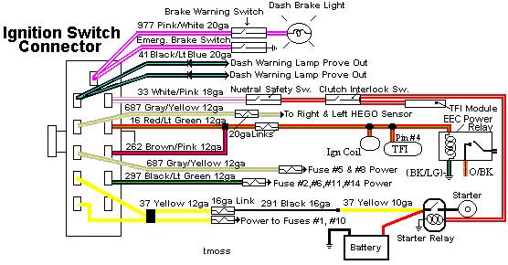
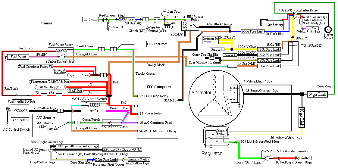
Diagrams courtesy of Tmoss & Stang&2birds

Ignition switch wiring
IgnitionSwitchWiring.gif


Fuel, alternator, A/C and ignition wiring
fuel-alt-links-ign-ac.gif


Next check the grounds, especially the computer

Grounds

Revised 28-Oct-2012 to add signal ground description & possible problems if it is bad

Grounds are important to any electrical system, and especially to computer controlled engines. In an automobile, the ground is the return path for power to get back to the alternator and battery.

Make sure that all the ground places are clean and shiny bare metal: no paint, no corrosion.

1.) The main power ground is from engine block to battery: it is the power ground for the starter & alternator. It bolts to the block on the driver’s side down next to the oil pressure sender near the lower front side of the engine.


2.) The secondary power ground is between the back of the intake manifold and the driver's side firewall. It is often missing or loose. It supplies ground for the alternator, A/C compressor clutch and other electrical accessories such as the gauges. The clue to a bad ground here is that the temp gauge goes up as you add electrical load such as heater, lights and A/C.

Any car that has a 3G or high output current alternator needs a 4 gauge ground wire running from the block to the chassis ground where the battery pigtail ground connects. The 3G has a 130 amp capacity, so you wire the power side with 4 gauge wire. It stands to reason that the ground side handles just as much current, so it needs to be 4 gauge too.

The picture shows the common ground point for the battery , computer, & extra 3G alternator ground wire as described above in paragraph 2. A screwdriver points to the bolt that is the common ground point.

The battery common ground is a 10 gauge pigtail with the computer ground attached to it.
Picture courtesy timewarped1972
ground.jpg


Correct negative battery ground cable.
86-93-mustang-oem-style-ground-cable-gif.56567


3.) The computer's main power ground (the one that comes from the battery ground wire) uses pins 40 & 60 for all the things it controls internally: it comes off the ground pigtail on the battery ground wire. Due to its proximity to the battery, it may become corroded by acid fumes from the battery.
In 86-90 model cars, it is a black cylinder about 2 1/2" long by 1" diameter with a black/lt green wire.
In 91-95 model cars it is a black cylinder about 2 1/2" long by 1" diameter with a black/white wire.
You'll find it up next to the starter solenoid where the wire goes into the wiring harness.

All the grounds listed in items 1,2 & 3 need to bolt to clean, shiny bare metal. A wire brush or some fine sandpaper is the best thing to use to clean the ground connections.


4.) All the sensors have a common separate signal ground. This includes the TPS, ACT, EGR, BAP, & VSS sensors. This ground is inside the computer and connects pin 46 to pins 40 & 60, which are the main computer grounds. If this internal computer ground gets damaged, you won't be able to dump codes and the car will have idle/stall/ performance problems

5.) The O2 sensor heaters have their own ground (HEGO ground) coming from the computer. This is different and separate from the O2 sensor ground. It is an orange wire with a ring terminal on it. It is located in the fuel injector wiring harness and comes out under the throttle body. It gets connected to a manifold or bolt on back of the cylinder head.

6.) The TFI module has 2 grounds: one for the foil shield around the wires and another for the module itself. The TFI module ground terminates inside the computer.

7.) The computer takes the shield ground for the TFI module and runs it from pin 20 to the chassis near the computer.


See http://assets.fluke.com/appnotes/automotive/beatbook.pdf for help for help troubleshooting voltage drops across connections and components. Be sure to have the maximum load on a circuit when testing voltage drops across connections. As current across a defective or weak connection, increases so does the voltage drop. A circuit or connection may check out good with no load or minimal load, but show up bad under maximum load conditions. .

Voltage drops should not exceed the following:
200 mV Wire or cable
300 mV Switch
100 mV Ground
0 mV to <50 mV Sensor Connections
0.0V bolt together connections

attachment.php


Extra grounds are like the reserve parachute for a sky diver. If the main one fails, there is always your reserve.

The best plan is to have all the grounds meet at one central spot and connect together there. That eliminates any voltage drops from grounds connected at different places. A voltage drop between the computer ground and the alternator power ground will effectively reduce the voltage available to the computer by the amount of the drop.


See the following website for some help from Tmoss (diagram designer) & Stang&2Birds (website host) for help on 88-95 wiring http://www.veryuseful.com/mustang/tech/engine/ Everyone should bookmark this site.

Complete computer, actuator & sensor wiring diagram for 91-93 Mass Air Mustangs
http://www.veryuseful.com/mustang/tech/engine/images/91-93_5.0_EEC_Wiring_Diagram.gif

Complete computer, actuator & sensor wiring diagram for 88-91 Mass Air Mustangs
http://www.veryuseful.com/mustang/tech/engine/images/88-91_5.0_EEC_Wiring_Diagram.gif

Ignition switch wiring
http://www.veryuseful.com/mustang/tech/engine/images/IgnitionSwitchWiring.gif

Fuel, alternator, A/C and ignition wiring
http://www.veryuseful.com/mustang/tech/engine/images/fuel-alt-links-ign-ac.gif

O2 sensor wiring harness
http://www.veryuseful.com/mustang/tech/engine/images/mustangO2Harness.gif

Vacuum diagram 89-93 Mustangs
http://www.veryuseful.com/mustang/tech/engine/images/mustangFoxFordVacuumDiagram.jpg

HVAC vacuum diagram
http://www.veryuseful.com/mustang/tech/engine/images/Mustang_AC_heat_vacuum_controls.gif

TFI module differences & pin out
http://www.veryuseful.com/mustang/tech/engine/images/TFI_5.0_comparison.gif

Fuse box layout
http://www.veryuseful.com/mustang/tech/engine/images/MustangFuseBox.gif

87-92 power window wiring
http://www.veryuseful.com/mustang/tech/engine/images/mustang87-92 PowerWindowWiring.gif

93 power window wiring
http://www.veryuseful.com/mustang/tech/engine/images/mustang93PowerWindows.gif

Visual comparison of the Ford Fuel Injectors, picture by TMoss:
http://www.veryuseful.com/mustang/tech/engine/images/Ford_Injector_Guide.jpg
 
  • Like
Reactions: 3 users
Man, I almost wish I had a mustang of my own to fight with. Community knowledge for mustangs is so much better than any other motor I've worked on.

Yea, bad grounds and/or bad ignition seem like the obvious first culprit. The ign switch definitely doesn't look happy so we're replacing it tonight. I'm really hoping we haven't fried both ECU's.
Incidentally, the engine DOES RUN like this, which is what confuses me so much. It actually runs very strong, makes enormous power, and sounds great in open loop. Once it hits closed loop, it wants to rev high and occassionally the RPMS will rise and fall for a few minutes.

One other point is that the tach will occasionally jump up about 500RPM. Has done this since day one.

I'll try to go over all the suggested stuff tonight. We're hoping to not have to replace the entire body harness, as we really just need the car to run for a few weeks while we either build a new wheelin' rig (cause the owner of the stang got a VI on his truck).


Someone wanna do me a favor though? Can someone actually confirm that ECU pin16 (TFI ign grnd) actually provides continuity to ground with ign on, and does NOT get any voltage? I've looked over the diagrams heaps of times, and logically, pin16 should not have voltage on it, but what do I know? Maybe ford does some really wonky stuff with their electrical?
IE: could someone just unplug their TFI with ignition on, and check the ign grnd pin for both voltage as well as continuity to grnd?
 
And now discovered the ignition switch is a bit flakey. Running out to grab a new one.
That said, I see ignition ground on the diagrams (usually from the ECU) but can't figure out how the ECU knows to turn on IGN grnd. Is that being handled by the ECU, or is that on the ign switch?
 
Well, couple more hours into it and no progress. Pulled all the sensors and check the ign grnds from the ECU again, still have 5V.
Decided to isolate the ECU entirely. Unplugged from the harness and wired it for power (two wires) and ground (two wires). No change.
Any chance someone can measure out pin 16 for me, with ignition on, for both voltage and continuity to ground? I'm starting to wonder if I'm just missing something, and those "grounds" aren't actually supposed to be ground and the voltage is somehow normal. It's either that or there's more ECU grounds that we don't know about and I'm not seeing on the schematics, or both our ECU's have failed in exactly the same manner. Gets expensive to test if we just buy another ECU and plug it in and see the same response because it blows up immediately.
 
To me it sounds like an issue with the o2 sensor harness....that would also blow the ecu right away. The reason is because the car runs till warm....o2 sensors don't start talking till warm. Not sure about mustangs but a lot of cars base their initial start up on a calculation of the last reading from the o2 sensors. The automatic o2 harness has a different ground path....thats why they don't interchange unless the pins are swapped. Without swapping pins it causes voltage to be sent into the computer internal ground circuit...destroying the computer ground circuit.

There is an easy fix if you can solder.

The computer uses o2 readings to adjust fuel trims and ignition timing. The harness for the o2 sensors runs on the right frame rail by k member mounting points and across the rack and pinion area. The ground for the o2 sensors is bolted to the firewall ( orange wire ).
 
  • Like
Reactions: 1 users
Let's start with some basics and see what they tell us...

Dump codes sticky

Look at the top of the 5.0 Tech forum where the sticky threads are posted. One of them is how to dump the computer codes. Codes may be present even if the CEL (Check Engine Light) isn’t on. You don’t need a code reader or scanner – all you need is a paper clip, or if your lady friend has a hair pin, that will do the job.
I highly suggest that you read it and follow the instructions to dump the codes. http://www.stangnet.com/mustang-forums/threads/how-to-pull-codes-from-eec4.889006/
 
  • Like
Reactions: 1 user
Just to be sure here...

The sensor reference ground for the ecu is called the sigrtn. The ecu supplies 5v source to most sensors (tps, bap, ect) the signal return is for this only and the ecu board traces can be burned if 12v is supplied to it. Vref is 5v, SigRtn is the ground path for Vref.... keep this in mind when testing.
 
  • Like
Reactions: 1 users
Just to be sure here...

The sensor reference ground for the ecu is called the sigrtn. The ecu supplies 5v source to most sensors (tps, bap, ect) the signal return is for this only and the ecu board traces can be burned if 12v is supplied to it. Vref is 5v, SigRtn is the ground path for Vref.... keep this in mind when testing.

Eyup. I'm just hoping to find someone who can actually test pin16 and pin45 on the ECU, to verify (on a working car) that there is no voltage seen there. I really don't think there should be, but I just find it super odd that both ECU's show exactly the same extraneous voltage. I'm 99% positive that both ECU's are toast (for the same reason), but we've found ourselves to be chasing our proverbial tails on a few Ford oddities before and I want to know beyond any doubt, that what I'm seeing is NOT expected.

I traced the ECU boards manually and didn't find any obvious burnt traces on either 16 or 45, but they both ultimately lead back to the larger IC in the center of the board, so I'm assuming something inside that IC blew out. Sure would be nice to have proper electrical diagrams and trace patterns for the ECU, as then I'd be able to pinpoint the exact point of failure, and intelligently deduce the CAUSE of the failure. (I spent a few weeks doing exactly that for a living, so I'm always annoyed when all electronics don't come with signal trace patterns).


Let's start with some basics and see what they tell us...

Dump codes sticky

Look at the top of the 5.0 Tech forum where the sticky threads are posted. One of them is how to dump the computer codes. Codes may be present even if the CEL (Check Engine Light) isn’t on. You don’t need a code reader or scanner – all you need is a paper clip, or if your lady friend has a hair pin, that will do the job.
I highly suggest that you read it and follow the instructions to dump the codes. http://www.stangnet.com/mustang-forums/threads/how-to-pull-codes-from-eec4.889006/

We've checked the codes many times. We only ever get codes for the TPS. For some reason the ignition thinks it's happy.

All that said, we're trying to track down another ECU, but until we're sure what caused both failures, we don't want to plug it in. Replaced the ignition switch and have gone over the wiring a hundred times, but just can't find anything wrong except the ECU itself. Owner says he's sure the O2 harness is correct for our year/application/ECU. I'm going to look it over again myself today hopefully. 12v being pushed into the sig-return causing the failure DOES make sense to me for the most part, but I find it very odd that doing so, would cause pin16 and 45 to create 5V, while not showing any signs of problems on the sig-return itself. Again, all sensors have been tested and they all look good. TPS code is all we ever get. Car runs very well, although a bit rich, and then out of nowhere, runs like crap and/or won't start.
 
Here's some help for the possible O2 sensor harness problem...

O2 Sensor harness interchange and modification

Originally Posted by 302EFI


Revised 16-Oct-2011 to add O2 sensor harness warnings
The wires for the 02's and low oil did not change throughout the years, they are all in the same place.
The main ones you need to worry about are (on the harness end (ECU) that plugs into the 02 plug) is:
\- 1. Lightblue / yellow
- 2. White / Purple
- 3. Purple / Yellow
The White/Purple & Purple/Yellow gets looped for a automatic ECU
The Purple/Yellow & Lightblue/Yellow for a manual ECU

?temp_hash=80c1e17d46ac51f7e7f8cbbe0869fbb0.jpg

Not all wires are shown for clarity and simplicity

See http://forums.corral.net/forums/gen...manual-auto-differences-year-differences.html for more O2 sensor wiring harness info

Basic premise to use with transmission swaps:
Only run a 5 speed trans O2 harness with an A9L. Do not run an Auto O2 sensor harness with an A9L. Doing so will damage the computer’s internal signal ground.
Only run an Auto trans O2 sensor harness with an A9P in a car that has an Auto trans. Using a 5 speed trans O2 sensor harness with an Auto trans will cause no crank problems.
See http://www.stangnet.com/mustang-forums/749974-computer-issue.html#post7490537 for Joel5.0’s fix to the computer internal signal ground.
The 4 cylinder O2 harness uses 4 wire O2 sensors. It probably won’t work correctly without modifying it.
 
Pin 45 is the bap/map signal to the ecu if you were to use an oscilloscope it would show up as a square wave that moves in frequency. Checking voltage with this plugged in will result in a voltage potential.

Pin 19 is the igngnd.... if you are seeing a difference in potential on this line check ecu grounds and ground to block it's a orange wire that attaches to the back of the cylinder head
 
Sorry, I actually said pins 16 and 45, but meant 16 and 47. Not sure what you're referencing.
All of my tests (checking for voltage on pins 16 and 47) are done on the ECU, with the harness completely disconnected. I just give the ECU 12V to pins 1, 37, 57, and grounds to pins 20, 40, 60.
I've also tested with the ECU plugged in, but cut the TPS signal wire off entirely to verify the 5V is coming from the ECU on the green wire (yes, also have it on the 5V reference orange where it belongs, but doesn't belong on that signal wire).
 
My brain. I built my own ecu. Just using the pinout for reference as to what you are looking for.

Pin 16 is fine if the tfi works it either will or wont.

Pin 47 is the tps signal take your reading with this plugged in.

You are reading erroneous voltages due to circuit flyback. Diodes bro diodes
 
Well, that's the thing. The TFI works sometimes, doesn't others, always does strange :poo:. IE: with ignition on, if we unplug and replug the TFI from the harness, fuel pump relay, and injectors trip, and sometimes the engine tries to crank for 1/2 a second. Seeing 5V on the ground wire at the TFI makes it real difficult to verify that it's actually ground. Same with TPS. We actually discovered the stray voltage (5V) coming out of the ECU pin 47 because we were trying to calibrate the TPS, but couldn't get the signal voltage low enough. Some times it'd read as low as 2V, while sometimes it'd show 7-8V. 5V reference was good, ground was ground, but that green wire was showing 5V, even after cutting the TPS off the wire entirely. Thus, that 5V is coming from the ECU.

Are you suggesting that the 5V we're seeing on sensor returns is normal?