wiring on new to me 87 gt

fsubrah51

New Member
Aug 31, 2011
8
0
0
Hey guys, I recently picked up an 87 gt ttop. The car is stock except for true duals with flowmaster 40's. I was going through everything to make sure it all checked out, and noticed my ac clutch won't engage. After some research I figured the problem was prbably at the relay.

The previous owner cut the red wire to the relay, and had it connected to two wires and two small capacitors. One of these wires goes to the backside of the fuse block, connecting behind the power window circuit breaker. The other wire ran to the inner fender and was just wrapped around a stud, not sure what the units called, but its where the starter solenoid connects to. When I disconnected those two wires, I had no power at the red wire that is supposed to go to the ac clutch relay, I lost the driver side power window, and the engine would turn over but not start, almost like I had no fuel or spark.

Has anyone seen or dealt with anything like this? I can get some pics tomorrow to show where the two random wires run.

Thanks guys
 
If I read correctly, red wire at the fuel injectors should have 12 volts with the key on. If i disconnect the two wires that were run by the previous owener I have 0 volts. From looking at schematics, it seems like the red inector wires are in the same section of wires as the power to the ac clutch relay. with now power at both points does that point to a bad eec relay?
 
A bad ECC relay would mean that you had no power to the computer.
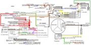
Go back and check out the diagrams.There is a A/C WOT cutoff relay and a low refrigerant cutoff switch. If the A/C has lost the refrigerant charge, the cluch will not engage.

Diagram courtsey of TMoss& Stang&2birds.
fuel-alt-links-ign-ac.gif
 

Attachments

  • fuel-alt-links-ign-ac.gif
    fuel-alt-links-ign-ac.gif
    83.1 KB · Views: 493
So I was out looking at the car a little earlier, and according to the schematic the wot ac switch has had the power wire cut, and a jumper with two capacitors has been added. One end goes to the power window circuit breaker, and the other goes to where the starter solenoid push connector is.

With the jumper disconnected I have 0 volts at the wot ac switch red wire. Also when I turn the key on, the fuel pump doesn't prime. I spoke with the kid that had the car before me, and according to him it was wired that way when he got the car. I'm completely stumped, and have no idea what they would have been bypassing with the jumper wires they ran.

I do know that the kid put in a nw steering column and ignition switch, is there an anti theft system that could be causing this, or possibly an incorrectly installed ignition switch?
 
Most people can't read circuit diagrams, but I am just the opposite. Without a circuit diagram, I find it very difficult to visualize what you are saying is cut & re-routed.
 
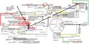
Excuse the mad paint skills. lol. this is basically what I have

fuelaltlinksignac.gif

Uploaded with ImageShack.us

Red wire to ac wot cutoff switch is cut. red wire is connected to two capacitors mounted in series and two jumper wires. one jumper goes to start relay, the 2nd goes to a key on power at the back of the fuse block
 

Attachments

  • fuelaltlinksignac.gif
    fuelaltlinksignac.gif
    70.5 KB · Views: 255
Restoring the wiring to the diagram is your best bet. That way you aren't guessing what goes where, what's protected by fuses and what isn't and what the correct wire size is for the load.


64326d1287785504-fusible-link-burned-up-need-help-87-93-5.0-mustang-fuse-links.gif


Fuse links come with a current rating just like fuses. A clue as to what current they are designed for is to look at the size wire they protect.

Choose the fuse according to the wire size.


Wire size current table:
http://www.stangnet.com/mustang-for...-wire-gauge-current-capacity-lenght-chart.gif


18 gauge wire = 5-8 amps
16 gauge wire = 10-12 amps
14 gauge wire = 15-17 amps
12 gauge wire = 20-25 amps
10 gauge wire = 30-40 amps
8 gauge wire = 50-60 amps.

Keep in mind that the wire size in the chart is for the circuit itself, not the size of the fuse link. The packages of fuse link repair material you can get at the auto parts stores also will have a current rating on them.

See Ford Fuel Injection » How To Solder Like a Pro for some excellent tips of soldering wires for best electrical performance.

Aircraft type circuit breakers are designed for low voltage DC applications and would be an excellent choice to replace fuse links. They come as a push/pull to reset button, and range from 1.5 amps to 60 amps and higher.

See Pilot Supplies, Avionics, and Homebuilt Aircraft Parts from Aircraft Spruce and Specialty Co. or http://www.wicksaircraft.com/catalogDetails.php or Home for circuit breakers and other items.

There is a store local to Orlando that does electronic surplus and has all kinds of circuit breakers. See index That's where I get most of my wiring supplies. There may be a similar type store in your area

For free automotive electrical training, see Automotive Training and Resource Site . I have personally reviewed the material and it is very good.


Tmoss's diagram is pretty good, and there is more on the web site where that came from.
See the following website for some help from Tmoss (diagram designer) & Stang&2Birds (website host) for help on 88-95 wiring Mustang FAQ - Wiring & Engine Info Everyone should bookmark this site.

Ignition switch wiring
http://www.veryuseful.com/mustang/tech/engine/images/IgnitionSwitchWiring.gif

Fuel, alternator, A/C and ignition wiring
http://www.veryuseful.com/mustang/tech/engine/images/fuel-alt-links-ign-ac.gif

Complete computer, actuator & sensor wiring diagram for 88-91 Mass Air Mustangs
http://www.veryuseful.com/mustang/tech/engine/images/88-91_5.0_EEC_Wiring_Diagram.gif

Complete computer, actuator & sensor wiring diagram for 91-93 Mass Air Mustangs
http://www.veryuseful.com/mustang/tech/engine/images/91-93_5.0_EEC_Wiring_Diagram.gif

Vacuum diagram 89-93 Mustangs
http://www.veryuseful.com/mustang/tech/engine/images/mustangFoxFordVacuumDiagram.jpg

HVAC vacuum diagram
http://www.veryuseful.com/mustang/tech/engine/images/Mustang_AC_heat_vacuum_controls.gif

TFI module differences & pinout
http://www.veryuseful.com/mustang/tech/engine/images/TFI_5.0_comparison.gif

Fuse box layout
http://www.veryuseful.com/mustang/tech/engine/images/MustangFuseBox.gif
 
thanks for the links to the aircraft surplus store. what type of circuit breakers would you recommend? Im gonna get to work replacing all of the fusible links next week

Low voltage push button style. They mount in a single 17/32" hole and have tab style screw terminals to connect the wiring.

sk2026.webp