
I read a past post you did where you stated that you dropped your upper arm mount down 1/2" for better camber curve. Do you have any pictures of this and could you explain how you developed your plot or discovered the 1/2" drop was better? I am working on a 65 so any help is appreciated. How is your progress on your conversion, will it be on the road this summer? Thanks again.
You are using an out of date browser. It may not display this or other websites correctly.
You should upgrade or use an alternative browser.
You should upgrade or use an alternative browser.
70 slantroof question about your Mustang II conversion
- Thread starter wildstang
- Start date

1970 slantroof
Founding Member
I wish it would be on the road this summer but I am probably looking at another year plus. I'm getting old so I don't work as fast as I once did and like a lot of others, the deeper I get into this project, the more work I find.
I'm not good at posting pictures but I will try.
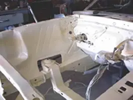
I took some poster board and did a full size plot of the front suspension using cardboard spindle and control arms pivoting on thumb tacks. I drew a vertical line on the board and plotted the camber curve with the stock suspensioon mounts on the R&C parts with 3" of drop and 4" of rebound. I then lowered the upper inner control arm pivot point by 1/2" and did it again. I could not lower the upper mount more than 1/2" and still get the upper arm mounting bolts in above the top of the frame rail. I cut the upper mount with a plasma cutter, trimmed the sides off, and tigged it back on. Then I cut a piece of 3/16" plate and curved it around the spring socket and tigged it in.
I hope this helps. The camber curve looks much better. I still have to check for binding in the upper ball joint and make any changes needed there in the control arm end. I am using stock control arms now since I am using 245x60x15 tires on 8x15" wheels and may need to make some changes to make them fit inside the front fenders. I will probably fabrricate some control arms later but saw no reason to do that when I'm not sure of the length yet. I think I will be ok but....
Howard
I'm not good at posting pictures but I will try.
I took some poster board and did a full size plot of the front suspension using cardboard spindle and control arms pivoting on thumb tacks. I drew a vertical line on the board and plotted the camber curve with the stock suspensioon mounts on the R&C parts with 3" of drop and 4" of rebound. I then lowered the upper inner control arm pivot point by 1/2" and did it again. I could not lower the upper mount more than 1/2" and still get the upper arm mounting bolts in above the top of the frame rail. I cut the upper mount with a plasma cutter, trimmed the sides off, and tigged it back on. Then I cut a piece of 3/16" plate and curved it around the spring socket and tigged it in.
I hope this helps. The camber curve looks much better. I still have to check for binding in the upper ball joint and make any changes needed there in the control arm end. I am using stock control arms now since I am using 245x60x15 tires on 8x15" wheels and may need to make some changes to make them fit inside the front fenders. I will probably fabrricate some control arms later but saw no reason to do that when I'm not sure of the length yet. I think I will be ok but....
Howard
Attachments
Thanks 1970 slantroof, the picture came through good, would you happen to have one of a close up of the upper arm mount? I does give me a good idea of what you did. So have you pre assembled the suspension to see how it works yet?
My wife is pressuring me know to get mine done and on the road this year, we'll see, I would like to but I am still at a bare shell that still need the paint stripped and finish body work done.
Thanks agian.
My wife is pressuring me know to get mine done and on the road this year, we'll see, I would like to but I am still at a bare shell that still need the paint stripped and finish body work done.
Thanks agian.
1970 slantroof
Founding Member
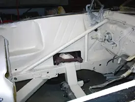
Yes I have the suspension assembled and the car is sitting on it's wheels now so I can roll it out of the shop to get my other vehicles on the hoist for service. I will try and post some pictures with the control arms bolted on. The stock upper control arm must be modified to work with the R&C kit. The opening must be enlarged to clear the spring pocket.
Howard
Howard
Attachments
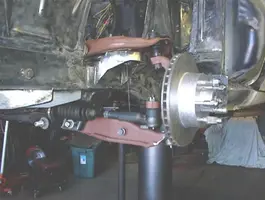
Thanks 70 slantroof. It looked like in the pictures that on one side your using a tubular lower and on the other you are using a stock lower? If you are going to use the stock lower are you using one of the strut rod eliminator kits or are you going to use the strut rod?
Very nice work, I am thinking of reinforcing the front the same way from the rail to the firewall, but I think I am going to do it on the outside of the engine bay.
Would you be kind of enough, if you still have them, is give the measurement of the upper, lower control arm and tire rod lengths you used to make your cardboard suspension mock up. I would like to try it and experiment with some different ideas. Also what are good camber rates ranges? I am looking to have a car that is mainly street duty but be able to handle the road twisties at speed, probably the same goals as you, so I don't need race car that handles like it is on rails. I am trying to find a source that would give acceptable ranges for the different suspension elements while designing a suspension. If you have them or know of a good book or source, I would be very gratefull if you could tell me. I know everything is a compromise but there must be acceptable ranges to stay within.
Thanks for the pictures, they are very helpfull. If you got anymore I would love to see them, especially any that are a closer shot of the upper mount. Sorry to keep bugging you, but when I get going on this again, I want to make sure I have everything lined up.
Thanks again for your help.
Very nice work, I am thinking of reinforcing the front the same way from the rail to the firewall, but I think I am going to do it on the outside of the engine bay.
Would you be kind of enough, if you still have them, is give the measurement of the upper, lower control arm and tire rod lengths you used to make your cardboard suspension mock up. I would like to try it and experiment with some different ideas. Also what are good camber rates ranges? I am looking to have a car that is mainly street duty but be able to handle the road twisties at speed, probably the same goals as you, so I don't need race car that handles like it is on rails. I am trying to find a source that would give acceptable ranges for the different suspension elements while designing a suspension. If you have them or know of a good book or source, I would be very gratefull if you could tell me. I know everything is a compromise but there must be acceptable ranges to stay within.
Thanks for the pictures, they are very helpfull. If you got anymore I would love to see them, especially any that are a closer shot of the upper mount. Sorry to keep bugging you, but when I get going on this again, I want to make sure I have everything lined up.
Thanks again for your help.
1970 slantroof
Founding Member
I have stock upper and lower control arms. I thought about putting the braces on the outside of the engine bay but was concerned about tire clearance. May not be an issue and it was easier to hook to the cowl if I put them inside.
The numbers I got may not be dead nuts but I believe they are close. I was looking more for the difference than the exact numbers but her is what I got on the camber.
Stock suspension
4" up travel = 3 deg. neg.
3" down travel = 1/2 deg. neg.
Modified (upper arm lowered 1/2")
4" up travel = 4 1/2 deg. neg.
3" down travel = 2 1/2 deg. pos.
I don't know where the cardboard pieces are right now but you can measure the MII stuff or stock whatever you are using. Just be sure to transfer the actual pivot points of the ball joints when mocking up the spindles and control arms.
I am looking for the same thing you are, a good handling street car but not an open track car. These new cars we drive have spoiled us.
As the car leans in a turn, you want the outside tire camber to go negative to maintain a flat contact patch and at the same time, the inside tire has to go negative in camber to maintain that contact patch. When circle track racing, we used to start with negative camber on the right side and positive camber on the left. How much can only be accurately measured with a tire pyrometer after some vigorous twistie driving. If 1/2" drop is too much, I can shim the upper control arm up a little to minimize the camber gain.
Howard
The numbers I got may not be dead nuts but I believe they are close. I was looking more for the difference than the exact numbers but her is what I got on the camber.
Stock suspension
4" up travel = 3 deg. neg.
3" down travel = 1/2 deg. neg.
Modified (upper arm lowered 1/2")
4" up travel = 4 1/2 deg. neg.
3" down travel = 2 1/2 deg. pos.
I don't know where the cardboard pieces are right now but you can measure the MII stuff or stock whatever you are using. Just be sure to transfer the actual pivot points of the ball joints when mocking up the spindles and control arms.
I am looking for the same thing you are, a good handling street car but not an open track car. These new cars we drive have spoiled us.
As the car leans in a turn, you want the outside tire camber to go negative to maintain a flat contact patch and at the same time, the inside tire has to go negative in camber to maintain that contact patch. When circle track racing, we used to start with negative camber on the right side and positive camber on the left. How much can only be accurately measured with a tire pyrometer after some vigorous twistie driving. If 1/2" drop is too much, I can shim the upper control arm up a little to minimize the camber gain.
Howard
I was hoping you had the upper and lower arm lengths because I don't have any of the stock arms any more unfortunately. If you happen to find the measurements and don't mind posting them, I would appreciate it.
You said you are using the lower arm also, are you using the strut rod like the stock or are you using one of the strut rod eliminator kits, pivot welds to the frame and a small bent tube bolts to your lower arm and new pivot point?
Thanks for your help.
You said you are using the lower arm also, are you using the strut rod like the stock or are you using one of the strut rod eliminator kits, pivot welds to the frame and a small bent tube bolts to your lower arm and new pivot point?
Thanks for your help.
1970 slantroof
Founding Member
Sorry, I forgot that in the last post. I am using the latest version of the strut rod eliminator kit from Rod & custom. He has redesigned those to be stronger. I like the new ones much better but you do have to cut the old bracket off the crossmember and weld a new one on.
I am tied up this week with doctor visits etc. but will try to find the cardboard parts I made. I have them out in the shop somewhere.
Howard
I am tied up this week with doctor visits etc. but will try to find the cardboard parts I made. I have them out in the shop somewhere.
Howard
Another question I forgot to ask was I assume you are going to use a sway bar, which one are you using and what about the front springs?
Thanks again.
Jim
Thanks again.
Jim
1970 slantroof
Founding Member
I got the springs from Rod&Custom but I don't remember the part no. I told him an HO 302 w/AC and a 5 speed, Alum. radiator and I took his recommendation as a starting point. I am going to run a 1" front sway bar to start because I have one. Who knows where I will end up.
Howard
Howard
1970 slantroof
Founding Member
I finally found the stuff and have a crude drawing to add. The dimensions did no come out too clear so I will repeat them here.
Lower control arm length pivot to pivot= 13 3/16"
Upper control arem length pivot to pivot= 8 1/8"
Vertical distance between upper & lower arm inner pivots= 9 7/16"
Spindle distance between pivot points= 10 1/16"
Upper a arm mount is 3 1/8" outboard of lower pivot
Spindle angle is approximatly 12 deg
This crude drawing IS NOT to any scale
Hope this helps,
Howard
I can't upload the drawing. Do youhave an e mail adderss I can send it to?
Lower control arm length pivot to pivot= 13 3/16"
Upper control arem length pivot to pivot= 8 1/8"
Vertical distance between upper & lower arm inner pivots= 9 7/16"
Spindle distance between pivot points= 10 1/16"
Upper a arm mount is 3 1/8" outboard of lower pivot
Spindle angle is approximatly 12 deg
This crude drawing IS NOT to any scale
Hope this helps,
Howard
I can't upload the drawing. Do youhave an e mail adderss I can send it to?
Thanks 70 slantroof, my email is [email protected] . I have a couple more questions, I may of asked but not sure, did you have to notch the outside frame rail for the spring clearance and do they do anything to compensate for the track width distance. The 65 mustang and mustang II are close to the same track width, but the 70 mustang is wider, I thing 2 or 3 inches. Thanks.
Similar threads


- Replies
- 49
- Views
- 2K
- Replies
- 49
- Views
- 2K
- Replies
- 5
- Views
- 755

