Progress Thread 93 LX father son project

ZAM93LX

Member
Oct 25, 2025
20
14
13
Indiana
I made a post in the welcome wagon about this but I'm going to start a progress thread here to keep all of the updates in one place.

Long story short when I was 21 I bought a 93 2.3 LX car and a 91 5.0 LX car, the 91 car was super rotted so my dad and I started a 5.0 swap, in the process of that my dad got sick with cancer and passed away. I let the car sit untouched for around 12 years and decided this year was the year I finish it. Ive been making some progress on it but I have some questions surrounding routing the vacuum lines and a few electrical connectors on the car I cant find mates for and some ground wire locations I need to install I used to be in some forums several years ago and decided this would be a good place to find some help and document the process going forward.

A little background on the car, its a 93 LX with a 91 5.0/AOD drivetrain. I swapped the engine, engine harness, dash, dash harness and ECU from the 91 car into this one. The engine was rebuilt by my dad and I. The rear end has been over hauled and swapped to 3.73 gears. Its been 5 lug converted and disc brake swapped on the rear as well, the engine bay was smoothed and under the hood, door jambs, hatch jambs and engine bay were painted forest green metallic and that's about where I stopped on it 12 years ago.

It has a long way to go still but the last few months I assembled the interior, put the fenders, doors and front bumper on and I've been sorting the engine harness wiring out and collecting and installing missing pieces like the PCV valve, new radiator and hoses, new water pump, new LMR headlight harness, wiring in a fuel pump relay since I didnt get the one from the donor car small things like that.

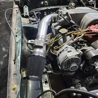
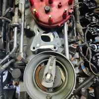
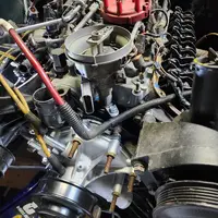
That's the background on the car, my current goal is to get the car running and move onto the next thing and just take it a step at a time. I attached pictures of what it looked like when I started working on it again and where it is now. I'm planning to document the journey here if for nothing else some entertainment and memories haha
 

Attachments

  • 20251026_193649.webp
    20251026_193649.webp
    792.4 KB · Views: 88
  • 20251026_193627.webp
    20251026_193627.webp
    732.2 KB · Views: 90
  • 20240915_200448.webp
    20240915_200448.webp
    453 KB · Views: 89
  • 20240728_192519.webp
    20240728_192519.webp
    624.5 KB · Views: 84
  • 20240728_192535.webp
    20240728_192535.webp
    939.8 KB · Views: 93
Last edited:
2000xp8 is correct. You'll need the wiring and vacuum diagrams for each year car. Now, the EVTM's are great but there's nothing better than the factory Ford wiring diagrams. They're large and foldout. These are what the factory Ford techs used in dealerships back in the day. You can physically trace every circuit to every connector and actuator in your car with these diagrams. They also include all the vacuum diagrams. I've bought one for every project I've ever done (and I've done a few). These are invaluable!

1991 Ford Mustang factory wiring diagram

1993 Ford Mustang factory wiring diagram
 
They are pinned differently. Good thread on this here:

I knew about the fuel pump relay, I wired in a fuel pump relay in the hatch to correct that issue
I bought the LMR headlight harness and stator plug to wire in the 2g alternator so I have that figured out but I'm unsure about pin locations on the body harness
I know theirs two circle 8 pin connectors behind the driver strut tower by the brake booster a grey one and a black one, they plug into each other but I'll have to look at the pin locations and see what's different between them, if I have to move some pins around thats not a huge deal.
The dash is out of the 91 5.0 car too so I'm not sure how much of the body harness of the 93 4 cylinder car comes through the firewall on the left side.
 
I am actually a ford tech and have access to the digital versions of the EVTMs but they only go back to 92, I started with ford in 2011 so my experience with early 90s cars and EVTMs is, limited at best haha
I think I mainly have it sorted out now and I have pretty much everything connected like it needs to be, since I swapped the dash harness in along with the engine and harness most things seem to be lining up, I need to check pinouts to make sure everything lines up but it looks like it does so far.
 
  • Like
Reactions: General karthief
Well I made some progress this weekend and had a set back also.
I installed the H pipe and o2 sensors, finished wiring in the fuel pump relay, wired in the 130 amp alternator and fitted my cheap amazon CAI intake
Then I removed the distributor added 5 qaurts of oil and tried to prime the oil pump, I spun the oil pump for several minutes, like 10 minutes with a milwaukee M18 fuel drill and couldnt get any oil out of the filter pad or to the rockers. I can hear oil gurgling in the pan and the oil pump drive shaft turns with resistance like its engaged to the pump but I just never get any oil pressure.
I have a feeling I know the answer but I was just wondering is it possible the drill doesn't spin fast enough to build oil pressure? Or does any one have any good ideas before I pull the pan and replace the pump, pickup tube, driveshaft and all associated gaskets? Because thats kind of where I'm at now

Actually after writing this post and doing my own research I've confirmed that I'm just an idiot and spun the pump the wrong direction for 5 minutes, I'm going to try spinning it the other direction and see how that goes.
 

Attachments

  • 20251101_183647.webp
    20251101_183647.webp
    334.9 KB · Views: 67
  • 20251101_203250.webp
    20251101_203250.webp
    526.7 KB · Views: 67
  • 20251101_200007.webp
    20251101_200007.webp
    651.8 KB · Views: 69
  • 20251101_201843.webp
    20251101_201843.webp
    849 KB · Views: 71
Last edited:
So it was just me, I spun the drill counter clockwise and pretty much immediately got oil coming up through the push rods so that was a relief
Then I cranked the engine over until the timing mark was on 0° with both valves closed on the number one cylinder and clocked the distributor, if someone could verify its correct I would appreciate it.
The rotor points to the lower intake manifold bolt hole on the driver side and sits under the number one post on the distributor cap so I think its correct
 

Attachments

  • 20251103_180344.webp
    20251103_180344.webp
    792.3 KB · Views: 74
  • 20251103_180615.webp
    20251103_180615.webp
    628.4 KB · Views: 64
Okay, so if I pull the number one spark plug and rotate the engine until I feel compression coming out of the spark plug hole and set the balancer back on zero the rotor should line up with the #1 terminal on the cap if I wasn't 180° degrees out correct? And if I was it'll be pointing the opposite direction?
 
You are correct on how to bring the motor up on the compression stroke. This is a four-stroke motor so when you are 180 degrees out the rotor will still point at the #1 cylinder terminal on the distributor cap.

If you want the motor to be dead on TDC when you bring it up on the compression stroke you need a stop device that screws into the spark plug hole that will contact the piston prior to TDC. Is it absolutely necessary? No but you will know if the timing pointer is off or not which is really nice when timing the motor. And if its off enough you can be a tooth off on the distributor. I have explained this before so I an not going to type all of it up again so go here if you are interested.

 
Okay, so if I pull the number one spark plug and rotate the engine until I feel compression coming out of the spark plug hole and set the balancer back on zero the rotor should line up with the #1 terminal on the cap if I wasn't 180° degrees out correct? And if I was it'll be pointing the opposite direction?
Take off the valve cover and after the intake valve goes down and up you will be on TDC as the line comes to the pointer...
 
  • Like
Reactions: ZAM93LX
I've made some progress the last couple of weekends so here's the updates. Since the last post I installed a new NSS switch and NSS harness because my harness was missing, I installed the TV cable and bracket because I was also missing those, installed a new throttle cable and bracket, installed and routed a new shifter cable, installed the drive shaft, installed a new speedo cable, speed sensor, speedo gear and started mocking up the contour electric fan to the radiator, finished wiring in a fuel pump relay and verified it works as intended since I didnt get the one out of the donor car.

I put a new battery in it and was able to actually check the fuel pump relay circuits and found the ground trigger from the ECM wasnt right, long story short I had one of the fuse able links grounded under a fender bolt so I was missing power to the ECM power relay. I fixed that issue and the pump primed and worked exactly like I wanted it to. I also attempted to crank the engine with the new battery and it was a no crank even with the starter solenoid jumped, I had power at the starter wire but no starter action, could've been a ground issue or a starter issue I didnt take the time to figure it out, I installed a mini starter and made a chassis to engine ground out of 4 gauge wire and was able to get the engine cranking with the key.

At this point I figured I had most of the necessary systems ready to attempt to actually start the car so I poured a few gallons of fuel in the tank and it all poured on the ground, I removed the fuel tank and found a small pin hole rusted through it so now I'm waiting on a new fuel tank, fan brackets and fan controller that should be here by next weekend so I'm hoping next weekend I'll actually have the car running. Thats my goal anyways. In my down time while I'm waiting I went ahead and removed the injector harness and re loomed and taped the whole engine bay harness with some cloth type tape to clean it up a little. I didnt take as many pictures as I probably should've but I was grinding trying to get this thing running.
 

Attachments

  • 20251121_152630.webp
    20251121_152630.webp
    482.1 KB · Views: 50
  • 20251120_182507.webp
    20251120_182507.webp
    835.2 KB · Views: 45
  • 20251123_173235.webp
    20251123_173235.webp
    693.4 KB · Views: 51
  • 20251123_183535.webp
    20251123_183535.webp
    685.2 KB · Views: 51
  • 20251122_200429.webp
    20251122_200429.webp
    606.6 KB · Views: 50
  • 20251122_192552.webp
    20251122_192552.webp
    756.1 KB · Views: 57
If you have rust in the tank be prepared to replace the pump or at a minimum the sock filter on the inlet of the pump. I would also recommend replacing the hose between the pump and the pump hanger as they tend to crack and leak fuel. I would also get a new fuel filter. You can see the hose I am talking about in this picture which is from my car ans is a modified hanger so not a stock one but you get the idea:

1763950994737.webp
 
  • Like
Reactions: ZAM93LX
Its getting a new pump and filler neck grommet while its out, the filter was replaced 12 years ago when I originally started the project and the cars never been run so it is new also. But I'll replace the hose too while I have it out.
I'm surprised it rusted, the car sat indoors for the last 12 years a rust hole in the gas tank was the last thing I expected.
 
That is strange but at least you know it will be 100% when it goes back together. Be sure to use dielectric grease on the wiring harness connection on the fuel pump hanger and also inspect the fuel tank wiring connector to the body harness connector. It is located here:

1763951774988.webp


Looks like this when the tank is out of the car (courtesy of Mustang5L5):

1763951803446.webp


They are known to get water in them and have issues. Inspect, clean if necessary, put dielectric grease in there, and reassemble.
 
  • Like
Reactions: Scrapla347
Yeah I'm not super upset about it anyways, I cant remember if it still has the 4 cylinder pump in it or not so I was planning to pull the tank and do the pump eventually anyways so I guess I'll know what pumps in it now
I usually put dielectric grease in any connectors I take apart but I'll be sure to do it on those connectors
Also thats a really clean gas tank, is that paint? It looks really good