

Yes, it was replaced by one I pulled from an early crown vic with a 5.0It had the H.O. firing order from the factory, because all EFI 5.0 Mustangs used the H.O. firing order. The X-cam has the same firing order.
Was the distributor moved at all while you had things apart?
You are using an out of date browser. It may not display this or other websites correctly.
You should upgrade or use an alternative browser.
You should upgrade or use an alternative browser.
Cam Change = Firing Order Change= Injector Change
- Thread starter Rjaaaaaa
- Start date


Cam dictates firing order.Yes, it was replaced by one I pulled from an early crown vic with a 5.0
If you are running the X cam, it is ground to open the valves in the HO firing order. If you are running the Vic cam, it isn't.
Right.Crown Vic's are not H.O motors right?
Is the distributor the same between H.O's and non H.O's?
Mostly if both were from roller cam cars.

Now bears the question is the TFI the same . There is like 4 different modules if I remember correctlyRight.
Mostly if both were from roller cam cars.
Thanks man,kinda what I was thinking-but wasn't sure.Right.
Mostly if both were from roller cam cars.
There are a few lolNow bears the question is the TFI the same . There is like 4 different modules if I remember correctly
Attachments

mikestang63
SN Certified Technician
EEC is in the A9l family for stick shift..
Did any of the MAF wires that were repinned when you converted from SD to MAF get fried? Pretty sure its pin 9 for the MAF signal, 40 or 60 for ground, 37 or 57 for power and I think 17 for the NSS
Is the TFI correct
Did any of the MAF wires that were repinned when you converted from SD to MAF get fried? Pretty sure its pin 9 for the MAF signal, 40 or 60 for ground, 37 or 57 for power and I think 17 for the NSS
Is the TFI correct


I would guess the tfi, the no start check list has a place in it to test it, will the computer pull codes?
Thanks man,kinda what I was thinking-but wasn't sure.
There are a few lol
I don't know ? The look the same, both are grey in color and mount on the dist.Crown Vic's are not H.O motors right?
Is the distributor the same between H.O's and non H.O's?
PO tells me it's an x-camCam dictates firing order.
If you are running the X cam, it is ground to open the valves in the HO firing order. If you are running the Vic cam, it isn't.
No, only the left side of the intake and main harness across firewallEEC is in the A9l family for stick shift..
Did any of the MAF wires that were repinned when you converted from SD to MAF get fried? Pretty sure its pin 9 for the MAF signal, 40 or 60 for ground, 37 or 57 for power and I think 17 for the NSS
Is the TFI correct
No, I removed 42# injectors because the left side was melted and I don't think this set up requires 42#, I don't know if the car was ever set up for the changes that were made.Did you replace the MAF when changing injector size?
no, it has a 70mm maf w/ 70mm BBK TBDid you replace the MAF when changing injector size?
Got the fuel problem resolved but the engine is still not running good. I can pull any 3 plug wires an don't see or hear any difference ????I would guess the tfi, the no start check list has a place in it to test it, will the computer pull codes?
TFI could this cause this type of problem? I couldn't compare it side by side because the original was melted but I do know it was grey.Thanks man,kinda what I was thinking-but wasn't sure.
There are a few lol
I have good spark at the plugs so I don't see how the TFI could come into play.
I agree that the cam dictates the firing order (spark) but the question at hand is, if the new cam required a change in the firing order then what happens to the injector order??Cam dictates firing order.
If you are running the X cam, it is ground to open the valves in the HO firing order. If you are running the Vic cam, it isn't.
TFI could this cause this type of problem? I couldn't compare it side by side because the original was melted but I do know it was grey.
I have good spark at the plugs so I don't see how the TFI could come into play.
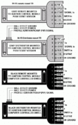
Here's a long,stolen post from another forum-some of the info isn't necessary for your situation-but basically explains what the tfi and pip actually do,and how I think its related to your issues.
I can't verify all info in this copied article (cause I didn't read it all
 )
)Is correct-but mostly useful.
"push start", TFI module.
This module was used to control the dwell time of the ignition coil, and provide a "limp home" mode, at base timing, in
case the timed
spark signal to the module is lost. Ford refers to the trigger signal as
PIP, (profile ignition
pickup). It is produced by a hall effect sensor in the distributor at system
voltage, and has
it's rising edge at 10 degrees before top dead center on the crankshaft. In
the case of the
distributor I'm working on, the duty cycle is 50% for all cylinders except #
1, which is
35%. This is used to identify #1 for fuel injector sequencing in some
applications.
This PIP signal is sent to the TFI module, and the ECU, (engine control
unit).
Which uses it to calculate RPM, and as a camshaft position indicator to
calculate timed
spark. The SPOUT signal, (timed spark out), is an output at system voltage
and 50% duty
cycle, and is sent back to the TFI module. It is delayed from the point of
PIP, and
calculated to occur so that it's rising edge coincides with the desired
timing angle to fire
the coil for the following cylinder in the firing order. The rotor on the
distributor routes
the coil secondary current to the appropriate spark plug. The TFI module
fires the coil
when it receives a rising edge of SPOUT. If it does not receive a SPOUT
before the next
PIP, it will fire the coil on that PIP, (base timing, limp home mode). It
appears to charge
the coil only when PIP is low.
There is also an input the TFI module from the starter circuit which is
supposed to
provide increased dwell time during cranking to offset decreased system
voltage. Also,
some printed information available on the module has stated that if the
"start" input is not
present during crank, it will latch into "limp home" mode and stay there
until the key has
been cycled and start signal restored.
I am, along with some others, are trying to use this module with a home
built
engine management computer, "Megasquirt", in particular. I've taken some
existing
Megasquirt codes and have modified them so they should work with the TFI
module but
have run into some difficulties, probably because of my lack of
understanding on exactly
how this module works.
The discussion has come up as to how the TFI handles the dwell time, which
is
fairly basic theory.
It is my understanding that the primary winding of the coil is connected to
system
voltage for a short period of time, say 4 or 5 ms. During this time, the
current ramps up,
opposed by the induced voltage in the windings, up to a maximum steady state
current
determined by the resistance of the circuit. When it's time to "fire', the
circuit to the
primary is opened. The field collapses, inducing a high voltage in the
primary, and a
proportional higher voltage in the secondary.
In a conventional Kettering, (points) system. the current is limited by a
ballast
resistor in series with the coil primary, and the time available to charge
the coil due to the
points being open and closed by a lobe on the distributor shaft.
Information on the TFI module states that it controls dwell with current
control.
The question is, what is the value of this controlled current, and when
does it
occur?
I say, the amount of energy available to fire the coil depends, not only on
the
inductance of the coil, but the amount of current flowing in the primary, at
the time of
current break. This is usually limited to 4 to 6 amps.
So, my theory is, the coil is not actually charged until SPOUT is received
.. At this
point, it is charged and fired in quick succession.
Others have said, the coil can be charged to it's fully charged state, any
time
before SPOUT goes high, with the current still limited to about the same
value, but then
decreased to some milliamp value until time to fire the coil, then break the
current, and
the coil will fire.


Use the firing order tech note I posted to answer your question and find out if your wiring is setup to work with the HO firing order.I agree that the cam dictates the firing order (spark) but the question at hand is, if the new cam required a change in the firing order then what happens to the injector order??
Remove the #1 & #3 spark plugs. Put your finger in #1 spark plug hole. Crank the engine over until you feel compression on #1 cylinder. Slowly turn the engine until the TDC mark and the timing pointer line up. Mark TDC on the balancer with chalk or paint. Put your finger in #3 spark plug hole and crank the engine 90 degrees. You should feel pressure trying to blow past your finger. If you do not feel pressure, repeat the process again. If you feel pressure, it is a HO engine.
No pressure the second time, remove spark plug #5. Put your finger in #1 spark plug hole. Crank the engine over until you feel compression on #1 cylinder. Put your finger in #5 spark plug hole and crank the engine 90 degrees. If you feel pressure now, the engine is not a HO model, no matter what it says on the engine.
Using a small carpenter or machinist square to mark the harmonic balancer off into 90 degree sections may be helpful here.
A 15/16 deep socket & breaker bar or ratchet may be used to turn the engine.
The HO firing order is 1-3-7-2-6-5-4-8.
Non HO firing order is 1-5-4-2-6-3-7-8
Do an end to the injector wring test to make sure that the injectors are properly sequenced for a HO engine and computer
Disconnect the main connector from the computer and pull it down so that you have good access to the computer side of the connector.
Place one voltmeter lead in pin 40 or 60 - they are both the main computer power ground. This lead does not change for any of the tests
Disconnect all the injector connectors from the injectors.
You will re-connect them one at a time to do the testing. Once you have checked an injector lead, disconnect it before testing the next injector. Fail to do this and you will get incorrect results
Turn the ignition switch to Run
Check pins 37 & 57; you should see 12 volts.
Computer wiring harness connector, wire side
Computer wiring harness connector, computer side side
Here are the HO injector wires that are different; check to see that you have 12 volts on them one at a time.
Connect injector #3, look for 12 volts on pin 12 on the computer. Disconnect the injector connector from the injector before testing the next wire.
Connect injector #7, look for 12 volts on pin 42 on the computer. Disconnect the injector connector from the injector before testing the next wire.
Connect injector #5, look for 12 volts on pin 14 on the computer. Disconnect the injector connector from the injector before testing the next wire.
Connect injector #4. look for 12 volts on pin 13 on the computer. You are finished now and can reconnect all the injector connectors to the injectors.
Similar threads
- Replies
- 7
- Views
- 342

- Replies
- 7
- Views
- 287
- Replies
- 4
- Views
- 310

- Replies
- 7
- Views
- 210

- Replies
- 11
- Views
- 288