
You are using an out of date browser. It may not display this or other websites correctly.
You should upgrade or use an alternative browser.
You should upgrade or use an alternative browser.
Fox Father son project
- Thread starter SHOme
- Start date
Sorry I haven't updated. We had a fire and burned up my house garage. Not the shop where theMustang is. I had to fire the contractor and have been completing the rebuild myself. Almost done. I have worked on the car a little. Mostly showing my son what to do and cutting him loose. He is taking advantage of YouTube. He is doing well. Below are pics of the finished shock towers. Scott Rod kit is awsome.
Attachments


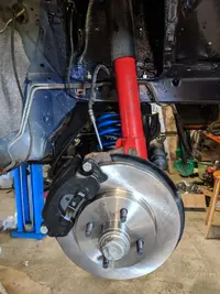

Here are some photos of the car. First thing is to address the shock towers. This is the only rust I can find. I need to pull the engine apart and see what it actually has in it. I would like to detune it some if that is possible. this car rips. I drive a tuned SHO and this car feels like it has the same power only more violent. I may be wrong but it is no where near stock. It looks to have 24 lb injectors. how much power can be made with 24 lb injectors? My son has his learners and cant drive on his own until May. He has not driven a stick but does ride a YZ250 so he understands a clutch. Once I identify the heads I will post and start asking questions. We just got the engine out yesterday. My next step is dropping the K member so my body man can access the tower area.
Fuel injector sizing & injector photos
Revised 26-Dec-2014 to add statement about figures are for flywheel HP and not rear wheel HP
Injector HP ratings: this flywheel HP, not rear wheel HP.
Divide flow rating by.5 and multiply the result by the number of injectors. This uses a 100% duty cycle. These ratings are for naturally aspirated engines at the flywheel.
Example:
19/.5 = 38, 38 x 8 = 304 HP
24/.5 = 48, 48 x 8 = 384 HP
30/.5 = 60, 60 x 8 = 480 HP
36/.5 = 72, 72 x 8 = 576 HP
42/.5 = 84, 84 x 8 = 672 HP
The preferred duty cycle is about 85% maximum, so for a safety factor multiply the final figure times .85.
19/.5 = 38, 38 x 8 = 304 HP x .85 = 258 HP
24/.5 = 48, 48 x 8 = 384 HP x .85 = 326 HP
30/.5 = 60, 60 x 8 = 480 HP x .85 = 408 HP
36/.5 = 72, 72 x 8 = 576 HP x .85 = 490 HP
42/.5 = 84, 84 x 8 = 672 HP x .85 = 571 HP
Remember that the above ratings are at 39 PSI. Increasing the pressure will effectively increase the flow rating. Example: a 19 lb injector will flow 24 lbs at 63 PSI, and a 24 lb injector will flow 30 lbs at 63 PSI.
See http://users.erols.com/srweiss/calcpchg.htm to get the calculators used in these examples.
Here's the duty cycle explanation. Duty cycle is how much of the time the intake is open the injectors are turned on. The 85% figure means that for 85% of the time the intake valve is open, the injectors are spraying. The idea is that you want some percentage of the duty cycle left over so that you have some room to grow the process.
If you are at 100% and you need more fuel, all you can do is turn up the fuel pressure. That means the whole fuel curve from idle to WOT is affected. Maybe you are already too rich at idle, and turning up the fuel pressure makes it worse. If you had some injector duty cycle left to play with, a custom tune could use that where it is needed. That would not over richen the whole range from idle to WOT.
If you did turn up the fuel pressure, you might be able to change the injector duty cycle to get the air/fuel mixture ratio you want since the injectors will have extra fuel delivery capability.
With larger than stock injectors or higher that stock fuel pressure, you will need an aftermarket MAF that matches the injector size. The MAF “lies” to the computer to get a fuel delivery schedule that meets the engine’s needs and isn’t too rich or too lean. The best strategy is an aftermarket MAF and a custom tune to insure the best air/fuel ratio over all the RPM range.
Don't forget to increase the fuel pump size when you increase injector size or significantly increase the fuel pressure
Diagram courtesy of Tmoss & Stang&2birds
See the following website for some help from Tmoss (diagram designer) & Stang&2Birds (website host) for help on 88-95 wiring http://www.veryuseful.com/mustang/tech/engine/ Everyone should bookmark this site.
Ignition switch wiring
Fuel, alternator, A/C and ignition wiring
Complete computer, actuator & sensor wiring diagram for 88-91 Mass Air Mustangs
Vacuum diagram 89-93 Mustangs
HVAC vacuum diagram
TFI module differences & pinout
Fuse box layout
I am a glass half full guy. I look at it as I got a much need garage clean outAwesome progress! Sorry to here about the fire. I hope you didn't loose much.
")
Gs1987GT
Active Member
Sorry to hear about your fire and lousy contractors. Unfortunately I've also been there and done that. Car is looking good! Glad to see your making some progress again. It's tough to find time, I also understand that.
Success. Fired up but ran bad at first.. Seemed one or more of the new injectors was sticking for a bit. Got timing set and it was still off. Replaced the mass air with another one I had laying around and she smoothed out. The one that I removed was from the hot motor I pulled. It made it run really lean. Shortly after that heater hose on the firewall came off. My son learned that hose clamps come in different sizes and the one he used was too big. We did put it in gear while on the lift and noticed the drivers side rear wheel was wobbling. Gonna switch it with the passenger side and try it to see if it is a bent axle or rim. I also notice there are no sway bars on this thing. I don't have any either. I guess whoever had this before removed them because it was a straight line car. If anyone has some they want to get rid of hit me up. The smile on my sons face was priceless. I don't know what brand of mufflers this thing has but it is loud, almost open header loud. I felt like I was at a NASCAR track. I'm going to cut the oil filter open and check it out and continue the break in this week. All goes well we will get it inspected after Thanksgiving.
Need a little help. One of the rocker studs keeps coming loose. The first time I chalked it up to it was just not tight from the builder. I researched and it appears these are supposed to be hand tight. So I did that and readjusted the rocker. Fired it up and ran it for 20 min at 2k rpm and it started making noise again. This time I locked it down tight with the nut and poly lock. Reinstalled and adjusted the rocker. Fired it up ran it for 15 min or so and it has come loose again. I doing something wrong? Should I put loc tight on it? Is this telling me something else is wrong?
Possibly a collapsed lifter. It’s pumped up with oil when you do the adjustment, but then can’t hold the pressure under load? That’s just a guess, but I don’t think a rocker with a poly lock would back off like that. Could try swapping two rockers and see if the problem follows the rocker or remains at the valve.
Similar threads
- Replies
- 24
- Views
- 1K
- Replies
- 1
- Views
- 210
- Replies
- 15
- Views
- 577
- Replies
- 5
- Views
- 337