
You are using an out of date browser. It may not display this or other websites correctly.
You should upgrade or use an alternative browser.
You should upgrade or use an alternative browser.
My biggest build yet.
- Thread starter dpea250
- Start date

Been busting my ass this weekend, motor is out of the truck and in the process of being cleaned little by little. One head needs machine work to remove a broken bolt i couldnt get out.
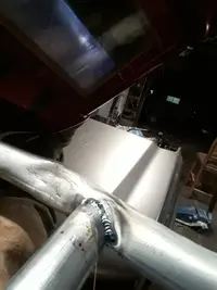
Started some fab work. Saw an idea to use 1" emt conduit and a bender to make light duty structures decided to give it a try. One side has a little more curve at the top and im wondering if i should try to straighten it or just let it be my dirty little secret.
The front end/radiator support is getting cut out and replaced with this removable tube frame one.
The tube bender i bought was absolute crap, even by harbor freight standars. It kinked the sharp bends bad. I was worried about the structural rigidity of it all at first till i started welding and im actually really impressed with how sturdy it is. Not fully welded up.... i gunked up my tungsten and its too late at night to grind a new tip. Figured ive made enough noise all day today and ill let my neighbors sleep.
After this is done ill be measuring up and cutting out pieces of the transmission tunnel.
Attachments


Update,
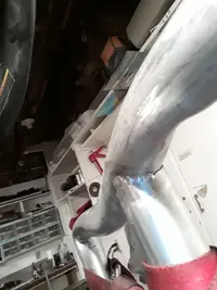
Finished up the tube front end and drilled out the 76 spot welds holding the old one on. After removal i put the fenders, bumper and hood on. It all fits!
This one sits a little lower cause i made it a little taller. Time to do some bracket fabrication with what i have.
Finished up the tube front end and drilled out the 76 spot welds holding the old one on. After removal i put the fenders, bumper and hood on. It all fits!
This one sits a little lower cause i made it a little taller. Time to do some bracket fabrication with what i have.
Attachments


and drilled out the 76 spot welds holding the old one on.
moving right along...
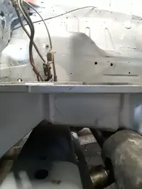
Ok so update, I cut out the tranny tunnel and opened up the firewall to about 21 inches where the tranny drops through. At first after cutting out the tunnel and setting it on the tranny i thought i did unnecessary work there, but after getting the motor in im glad i did it.
For the guys who want to drop in an LS with a 4l80e transmission you probably wont have to cut away as much as i did ,but the verticle section where the gas peddal sits will probably have to go. I think the fit is just too tight. The rest though you can probably get away with an aggressive message of the tunnel.
Motor looks like it will fit without too much issue and I might be able to run headers or a manifold without cutting out my fender wells.
Ive got everything pretty much where i want it side to side. Just have to get the crank angle just right. The plan is to make an adjustable angle mount.
I cut off the motor side of the truck mount and the body side of the stang mount. I will make a cradle bracket, if that makes sense, on each and weld one side to my 2 inch pipe. The pipe will act as my pivot point and onve ive got the ideal angle i want (im going for 3° tilted back) ill weld them in place and start working on my cross member. Because that mount is likely going to look like crap and will definately be bulkey I will use that as a negative to make a jig that i can use to make a nice tucked in tight mount hopefully with less unneeded welds.
Also got the front end frame mostly finished i stopped cause i spent 2 days straight on in and a little tired from it.
Now its time for a photo dump.
Attachments


Alsoit looks like I wont have to worry about hood clearance if i get a car intake manifold or a low clearance one like the holley lo-ram, which is the rout i would probably end up going anyways, boost and maybe a little spray is the end goal here and i dont trust the composite manifolds, ive heard of the LS2 handling it well but dont want to take my chances and like the security you get from metal under pressure.


Quick update first mount has been made.
Not too happy with the look of the welds, the jig has some tight spots and all i have is a stick welder to work with on it, i dont trust the tig with something this heavy duty. After it cools off ima go in and grind them smooth and check for imperfections. May turn the heat up as hot as she will go in 110. Its amost all 3/8 steel i beveled the crap out of it to ensure good pen so im not worried there. The mounts are solid this time around. I may end up making some poly bushed ones when ive got a mig.
Not too happy with the look of the welds, the jig has some tight spots and all i have is a stick welder to work with on it, i dont trust the tig with something this heavy duty. After it cools off ima go in and grind them smooth and check for imperfections. May turn the heat up as hot as she will go in 110. Its amost all 3/8 steel i beveled the crap out of it to ensure good pen so im not worried there. The mounts are solid this time around. I may end up making some poly bushed ones when ive got a mig.
progress has slowed a little, but is still being made decided on a different route for mounting going with poly bushed mounts. Got one made then ran out of gas. Used 3/8 steel as the base plate and 1/8 steel sides and 1x2x1/8 tube for the center support


Wiring harness has had each plug isolated and fuel injector plugs brought back together. That's not ready for pics yet lol gonna spend the rest of the day getting the other side if this mount fitted and ready to weld.
Wiring harness has had each plug isolated and fuel injector plugs brought back together. That's not ready for pics yet lol gonna spend the rest of the day getting the other side if this mount fitted and ready to weld.
indeed it is. The body side of the mount is a little overbuilt, I was worried about the overhang letting it flex too much. Made from 1/4" 3.5"x3.5" angle. Stick welded to a borderline structural code lol. Fits beautifully though.That mount is looking heavy duty now!
I know that one side is a little shorter but it was scrap and it was sooooo close to perfect I couldn't justify not using it lol. The short bit does help the mount slide out the front too.
That's not something I even thought about. Looks like I've got just a little work left to do on this one.Mounts look great! One question about them though, are you planning to drill a drainage hole since they're oriented that way?
Good lookin out man!
")
After you drill the drainage hole you could box them in as well, that would help alleviate any problems with anything collecting there.
After you drill the drainage hole you could box them in as well, that would help alleviate any problems with anything collecting there.
I had thought about boxing them in but it would make them difficult to remove perhaps a head shield over it? I was thinking of doing that anyway because the exhaust manifold will be coming a little close to the poly inserts. I could also open up the bottom a bit more than a small drain hole as well. Make the a picture frame of it if that makes sense.
I don't know if I can describe what I mean but I'll try. Weld a top on the long portion of the verticals and have it turn down to the lower before it gets to the mount. Leave the mounting holes and bracket exposed as they are now. The top that I'm talking about would basically totally enclose the pocket you have exposed AND give you a location to drill/tap a hole or 2 should you decide to install a heat shield over the mount. If it were me, I'd trim the lower plate back to expose the bottom of the engine mount and weld the top portion that I'm thinking of to the bottom to form a ~90 degree angle, thereby eliminating another potential pocket for anything to collect in. It looks to me that the vertical sections should be plenty strong to support the engine for that short section. They don't really need the fore and aft reinforcement that the bottom plate provides. I applaud the thought of over building it that way, but it can also be a catch all for oil, water, mud, etc that could build up over time and sit right under your mount. By the looks of the thickness of the vertical supports you could add a top plate without interfering with the frame mounting bolts.


I tried to draw a sketch of what I'm thinking and I'm posting them as well.
Hopefully this will help explain better than my description....Similar threads
- Replies
- 8
- Views
- 179
- Replies
- 20
- Views
- 393
- Replies
- 10
- Views
- 538
- Replies
- 10
- Views
- 4K