Code 42 & 92 (engine running) System rich - Fuel control or (memory) System was rich for 15 seconds or more (no HO2S switching) - Fuel control. Look for leaking injectors, fuel pressure too high, cylinder(s) not firing due to bad ignition.
Code 42 passenger side sensor, as viewed from the driver's seat
Code 92 is the driver side sensor, as viewed from the driver's seat..
The following is a Quote from Charles O. Probst, Ford fuel Injection & Electronic Engine control:
"When the mixture is lean, the exhaust gas has oxygen, about the same amount as the ambient air. So the sensor will generate less than 400 Millivolts. Remember lean = less voltage.
When the mixture is rich, there's less oxygen in the exhaust than in the ambient air , so voltage is generated between the two sides of the tip. The voltage is greater than 600 millivolts. Remember rich = more voltage.
Here's a tip: the newer the sensor, the more the voltage changes, swinging from as low as 0.1 volt to as much as 0.9 volt. As an oxygen sensor ages, the voltage changes get smaller and slower - the voltage change lags behind the change in exhaust gas oxygen.
Because the oxygen sensor generates its own voltage, never apply voltage and never measure resistance of the sensor circuit. To measure voltage signals, use an analog voltmeter with a high input impedance, at least 10 megohms. Remember, a digital voltmeter will average a changing voltage." End Quote
Testing the O2 sensors 87-93 5.0 Mustangs
Measuring the O2 sensor voltage at the computer will give you a good idea of how well they are working. You'll have to pull the passenger side kick panel off to gain access to the computer connector. Remove the plastic wiring cover to get to the back side of the wiring. Use a safety pin or paper clip to probe the connections from the rear.
Backside view of the computer wiring connector:
87-90 5.0 Mustangs:
Computer pin 43 Dark blue/Lt green – LH O2 sensor
Computer pin 29 Dark Green/Pink – RH O2 sensor
The computer pins are 29 (LH O2 with a dark green/pink wire) and 43 (RH O2 with a dark blue/pink wire). Use the ground next to the computer to ground the voltmeter. The O2 sensor voltage should switch between .2-.9 volt at idle.
91-93 5.0 Mustangs:
Computer pin 43 Red/Black – LH O2 sensor
Computer pin 29 Gray/Lt blue – RH O2 sensor
The computer pins are 29 (LH O2 with a Gray/Lt blue wire) and 43 (RH O2 with a Red/Black wire). Use the ground next to the computer to ground the voltmeter. The O2 sensor voltage should switch between .2-.9 volt at idle.
Testing the O2 sensors 94-95 5.0 Mustangs
Measuring the O2 sensor voltage at the computer will give you a good idea of how well they are working. You'll have to pull the passenger side kick panel off to gain access to the computer connector. Remove the plastic wiring cover to get to the back side of the wiring. Use a safety pin or paper clip to probe the connections from the rear. The computer pins are 29 (LH O2 with a red/black wire) and 27 (RH O2 with a gray/lt blue wire). Use pin 32 (gray/red wire) to ground the voltmeter. The O2 sensor voltage should switch between .2-.9 volt at idle.
There is a fuse link for the O2 sensor heater power. According to Ranchero50, it is in the wiring near the passenger side hood hinge. Measuring the voltages will give a clue if it has shorted to the O2 sensor signal lead. The O2 sensor voltage should switch between .2-.9 volt at idle.
Code 34 Or 334 - EGR voltage above closed limit –
Revised 26-Sep-2011 to add EGR cleaning and movement test for pintle when vacuum is applied to diaphragm
Failed sensor, carbon between EGR pintle valve and seat holding the valve off its seat. Remove the EGR valve and clean it with carbon remover. Prior to re-installing see if you can blow air through the flange side of the EGR by mouth. If it leaks, there is carbon stuck on the pintle valve seat clean or, replace the EGR valve ($85-$95).
Recommended procedure for cleaning the EGR:
Conventional cleaning methods like throttle body cleaner aren’t very effective. The best method is a soak type cleaner used for carburetors. If you are into fixing motorcycles, jet skis, snowmobiles or anything else with a small carburetor, you probably have used the one gallon soak cleaners like Gunk or Berryman. One of the two should be available at your local auto parts store for $22-$29. There is a basket to set the parts in while they are soaking. Soak the metal body in the carb cleaner overnight. Don’t immerse the diaphragm side, since the carb cleaner may damage the diaphragm. If you get any of the carb cleaner on the diaphragm, rinse it off with water immediately. Rinse the part off with water and blow it dry with compressed air. Once it has dried, try blowing through the either hole and it should block the air flow. Do not put parts with water on them or in them in the carb cleaner. If you do, it will weaken the carb cleaner and it won’t clean as effectively.
Gunk Dip type carb & parts soaker:
If you have a handy vacuum source, apply it to the diaphragm and watch to see if the pintle moves freely. Try blowing air through either side and make sure it flows when the pintle retracts and blocks when the pintle is seated. If it does not, replace the EGR.
If the blow by test passes, and you have replaced the sensor, then you have electrical ground problems. Check the resistance between the black/white wire on the MAP/BARO sensor and then the black/white wire on the EGR and the same wire on the TPS. It should be less than 1.5 ohm. Next check the resistance between the black/white wire and the negative battery post. It should be less than 1.5 ohm.
Note that all resistance tests must be done with power off. Measuring resistance with a circuit powered on will give false readings and possibly damage the meter.
Let’s put on our Inspector Gadget propeller head beanies and think about how this works:
The EGR sensor is a variable resistor with ground on one leg and Vref (5 volts) on the other. Its’ resistance ranges from 4000 to 5500 Ohms measured between Vref & ground, depending on the sensor. The center connection of the variable resistor is the slider that moves in response to the amount of vacuum applied. The slider has some minimum value of resistance greater than 100 ohms so that the computer always sees a voltage present at its’ input. If the value was 0 ohms, there would be no voltage output. Then the computer would not be able to distinguish between a properly functioning sensor and one that had a broken wire or bad connection. The EGR I have in hand reads 700 Ohms between the slider (EPV) and ground (SIG RTN) at rest with no vacuum applied. The EGR valve or sensor may cause the voltage to be above closed limits due to the manufacturing tolerances that cause the EGR sensor to rest at a higher position than it should.
The following sensors are connected to the white 10 pin connector (salt & pepper engine harness connectors)
This will affect idle quality by diluting the intake air charge
Code 10 is a spacer code and tells the scanner/code reader that the computer is ready to dump codes.
Code 85 CANP solenoid - The Carbon Canister solenoid is inoperative or missing.
Revised 11 –Jan_2015 to add warning about vacuum leaks due to deteriorated hose or missing caps on vacuum lines when the solenoid is removed.
Check vacuum lines for leaks and cracks. Check electrical wiring for loose connections, damaged wiring and insulation. Check solenoid valve operation by grounding the gray/yellow wire to the solenoid and blowing through it.
The computer provides the ground for the solenoid. The red wire to the solenoid is always energized any time the ignition switch is in the run position.
If you disconnected the carbon canister and failed to properly cap the vacuum line coming from under the upper intake manifold, you will have problems. You will also have problems if the remaining hose coming from under the upper intake manifold or caps for the vacuum line are sucking air.
Charcoal canister plumbing - one 3/8" tube from the bottom of the upper manifold to the rubber hose. Rubber hose connects to one side of the canister solenoid valve. Other side of the solenoid valve connects to one side of the canister. The other side of the canister connects to a rubber hose that connects to a line that goes all the way back to the gas tank. There is an electrical connector coming from the passenger side injector harness near #1 injector that plugs into the canister solenoid valve. It's purpose is to vent the gas tank. The solenoid valve opens at cruse to provide some extra fuel. The canister is normally mounted on the passenger side frame rail near the smog pump pulley.
Connecting the gas tank vent line directly to the intake manifold will result in fuel vapor being constantly sucked into the intake manifold. There is unmetered fuel that the computer cannot adjust for. The result is poor idle and poor fuel economy.
It does not weigh but a pound or so and helps richen up the cruse mixture. It draws no HP & keeps the car from smelling like gasoline in a closed garage. So with all these good things and no bad ones, why not hook it up & use it?
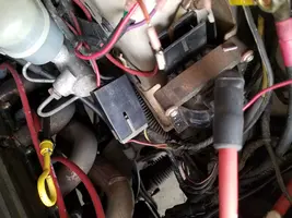
The purge valve solenoid connector is a dangling wire that is near the ECT sensor and oil filler on the passenger side rocker cover. The actual solenoid valve is down next to the carbon canister. There is about 12"-16" of wire that runs parallel to the canister vent hose that comes off the bottom side of the upper intake manifold. That hose connects one port of the solenoid valve; the other port connects to the carbon canister.
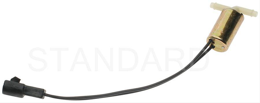
The purge valve solenoid should be available at your local auto parts store.
Purge valve solenoid:
The carbon canister is normally mounted on the passenger side frame rail near the smog pump pulley.
Carbon Canister:
Code 29 - Vehicle Speed Sensor (VSS) is an electronic sender mounted on the speedo pickup gear on the trans. It works the cruse control for both 5 speed and auto trans cars. The VSS is used to tell the computer to speed up the idle as you slow to a stop. This helps keep the engine from stalling when you slow down for a stop sign or stop light.
Check to see if the electrical connector is plugged into it. Clean the connector & contacts with non flammable brake parts cleaner prior to replacing the sensor, as that may fix the problem. The sensor cost is under $30 and it is easy to replace.
Code 66 or 157 MAF below minimum test voltage.
Revised 10-Feb-2014 to add 95-95 Mustang code 157 and 94-95 ECC diagram
Insufficient or no voltage from MAF. Dirty MAF element, bad MAF, bad MAF wiring, missing power to MAF. Check for missing +12 volts on this circuit. Check the two links for a wiring diagram to help you find the red wire for computer power relay switched +12 volts. Check for 12 volts between the red and black wires on the MAF heater (usually pins A & B). while the connector is plugged into the MAF. This may require the use of a couple of safety pins to probe the MAF connector from the back side of it.
Computer connector for 88-93 5.0 Mustangs
Diagrams courtesy of Tmoss and Stang&2Birds
ECC Diagram for 88-90 5.0 Mustangs
ECC Diagram for 91-93 5.0 Mustangs
94-95 Diagram for 94-95 5.0 Mustangs
There are three parts in a MAF: the heater, the sensor element and the amplifier. The heater heats the MAF sensor element causing the resistance to increase. The amplifier buffers the MAF output signal and has a resistor that is laser trimmed to provide an output range compatible with the computer's load tables. Changes in RPM causes the airflow to increase or decrease, changing the voltage output.. The increase of air across the MAF sensor element causes it to cool, allowing more voltage to pass and telling the computer to increase the fuel flow. A decrease in airflow causes the MAF sensor element to get warmer, decreasing the voltage and reducing the fuel flow.
The MAF element is secured by 2 screws & has 1 wiring connector. To clean the element, remove it from the MAF housing and spray it down with electronic parts cleaner or non-inflammable brake parts cleaner (same stuff in a bigger can and cheaper too).
89-90 Model cars: Measure the MAF output at pins C & D on the MAF connector (dark blue/orange and tan/light blue) or at pins 50 & 9 on the computer. Be sure to measure the sensor output by measuring across the pins and
not between the pins and ground.
91-95 Model cars: Measure the MAF output at pins C & D on the MAF connector light blue/red and tan/light blue) or at pins 50 & 9 on the computer. Be sure to measure the sensor output by measuring across the pins and
not between the pins and ground.
At idle = approximately .6 volt
20 MPH = approximately 1.10 volt
40 MPH = approximately 1.70 volt
60 MPH = approximately 2.10 volt
Check the resistance of the MAF signal wiring. Pin D on the MAF and pin 50 on the computer (dark blue/orange wire) should be less than 2 ohms. Pin C on the MAF and pin 9 on the computer (tan/light blue wire) should be less than 2 ohms.
There should be a minimum of 10K ohms between either pin C or D on the MAF wiring connector and pins A or B. Make your measurement with the MAF disconnected from the wiring harness.
Actually MAF pins C & D float with reference to ground. The signal output of the MAF is a differential amplifier setup. Pins C & D both carry the output signal, but one pin's output is inverted from the other. The difference in signal between C & D is what the computer's input circuit is looking for. The difference in the two outputs helps cancel out electrical noise generated by the ignition system and other components. Since the noise will be of the same polarity, wave shape and magnitude, the differential input of the computer electronically subtracts it from the signal. Then it passes the signal on to an Analog to Digital converter section inside the computer's CPU chip.
Code 96 causes & tests 91-93 models. – KOEO- Fuel pump monitor circuit shows no power - Fuel pump relay or battery power feed was open - Power / Fuel Pump Circuits. The fuel pump circuit lost power at one time or another.
Revised 24-Mar-2017 to add text about the A/C Wide Open Throttle relay and using the wire colors to identify which relay is the fuel pump relay
Clear the codes by disconnecting the battery and turning on the headlights for about 5 minutes before reconnecting the battery. This will clear any remaining codes. Drive the car for several days and dump the codes again. In many cases, this clears the 96 code.
Look for a failing fuel pump relay, bad connections or broken wiring. On 91 model cars, the fuel pump relay is under the driver’s seat. The fuel pump relay is located under the Mass Air Meter on Fox bodied stangs built after 91. It can be confused with the A/C Wide Open Throttle relay which is in the same area. Use the wire colors as shown in the diagram below to identify which relay is the fuel pump relay.
Diagram of the fuel pump wiring for 91-93 cars.
Look for power at the fuel pump - the fuel pump has a connector at the rear of the car with a pink/black wire and a black wire that goes to the fuel pump. The pink/black wire should be hot when the test connector is jumpered to the test position. To trick the fuel pump into running, find the ECC test connector and jump the connector in the lower RH corner to ground. No voltage when jumpered, check the fuel pump relay and fuse links.
Power feed: Look for 12 volts at the pink/black wire (power source for fuel pump relay). No voltage or low voltage, bad fuse link, bad wiring, or connections. Remember that on 92 or later models the fuel pump relay is located under the Mass Air meter. Watch out for the WOT A/C control relay on these cars, as it is located in the same place and can easily be mistaken for the fuel pump relay.
Relay: Turn on the key and jumper the ECC test connector as previously described. Look for 12 volts at the dark green\yellow wire (relay controlled power for the fuel pump). No voltage there means that the relay has failed, or there is a broken wire in the relay control circuit.
Be sure to closely check the condition of the relay, wiring & socket for corrosion and damage.
91-93 Models:
Using the diagram, check the dark green/yellow wire from the fuel pump relay: you should see 12 volts or so. If not the relay has failed or is intermittent. Check the inertia switch: on a hatch it is on the driver’s side by the taillight. Look for a black rubber plug that pops out: if you don't find it, then loosen up the plastic trim. Check for voltage on both sides of the switch. If there is voltage on both sides, then check the Pink/black wire on the fuel pump relay: it is the power feed to the fuel pump. Good voltage there, then the fuel pump is the likely culprit since it is getting power. No voltage there, check the Pink/black wire, it is the power feed to the fuel pump relay & has a fuse link in it. Good voltage there & at the dark green/yellow wire, swap the relay.
All testing is done with the ignition switch in the Run position. Do not forget this crucial step.
The pink/black wire should have the same voltage as the battery positive terminal +/- 0.25 volt. If not, then the fuse link for the fuel pump has opened up.
With the test jumper in place the green/yellow wire should be the same voltage as the pink/black wire +/- 0.25 volt.
If not, look at the red wire: should have the same voltage as the battery positive terminal +/- 0.25 volt.
If not, then check the yellow wire on the EEC relay located on top of the computer. This one is hard to get to. It should have the same voltage as the battery positive terminal +/- 0.25 volt. If not, then the fuse link for the computer has opened up.
If the red wire does not have the same voltage as the battery positive terminal +/- 0.25 volt and the yellow wire on the EEC relay does, then check the red/green wire on the EEC relay. It should have the same voltage as the battery positive terminal +/- 0.25 volt. If not, then the ignition switch is defective or the fuse link in the ignition wiring harness has opened up, or the EEC relay is defective.
All testing is done with the ignition switch in the Run position. Do not forget this crucial step.
The pink/black wire s should have the same voltage as the battery positive terminal +/- 0.25 volt. If not, then the fuse link for the fuel pump has opened up.
With the test jumper in place the green/yellow wire should be the same voltage as the pink/black wire +/- 0.25 volt.
If not, look at the red wire: should have the same voltage as the battery positive terminal +/- 0.25 volt.
If not, then check the yellow wire on the EEC relay located on top of the computer. This one is hard to get to. It should have the same voltage as the battery positive terminal +/- 0.25 volt. If not, then the fuse link for the computer has opened up.
If the red wire does not have the same voltage as the battery positive terminal +/- 0.25 volt and the yellow wire on the EEC relay does, then check the red/green wire on the EEC relay. It should have the same voltage as the battery positive terminal +/- 0.25 volt. If not, then the ignition switch is defective or the fuse link in the ignition wiring harness has opened up, or the EEC relay is defective.
Diagram courtesy of Tmoss & Stang&2birds
See the following website for some help from Tmoss (diagram designer) & Stang&2Birds (website host) for help on 88-95 wiring
http://www.veryuseful.com/mustang/tech/engine/
Ignition switch wiring
http://www.veryuseful.com/mustang/tech/engine/images/IgnitionSwitchWiring.gif
Fuel pump, alternator, ignition & A/C wiring
http://www.veryuseful.com/mustang/tech/engine/images/fuel-alt-links-ign-ac.gif
Computer,. actuator & sensor wiring
http://www.veryuseful.com/mustang/tech/engine/images/88-91_5.0_EEC_Wiring_Diagram.gif
Fuse panel layout
http://www.veryuseful.com/mustang/tech/engine/images/MustangFuseBox.gif
Vacuum routing
http://www.veryuseful.com/mustang/tech/engine/images/mustangFoxFordVacuumDiagram.jpg

 . Enjoy driving a leak free 5.0 Mustang!