If you were successful dumping the codes using the jumper method or an Equus Digital Ford Code Reader 3145, then your signal ground/pin 46 problems are non existent.
The STI has a gray connector shell and a white/red wire. It comes from the same bundle of wires as the self test connector.
Here's why...
The grey/red wire (pin 46) is signal ground for the computer. It provides a dedicated ground for the EGR, Baro, ACT, ECT, & TPS sensors as well as the ground to put the computer into self-test mode. As long as you are successful dumping the codes by using the gray/red wire on the diagnostic connector for the ground when dumping, the computer’s internal ground on pin 46 is good.
If this ground is bad, none of the sensors mentioned will work properly. That will severely affect the car's performance. You will have hard starting, low power and drivability problems. Since it is a dedicated ground, it passes through the computer on its way to the computer main power ground that terminates at the battery pigtail ground. It should read less than 1 ohm when measured from anyplace on the engine harness with the battery pigtail ground as the other reference point for the ohmmeter probe.
Code 67
Revised 4 Sep 2016 to add the necessity for both clutch being depressed and the transmission is in neutral to dump the codes on a 5 speed transmission car.
Cause of problem:
Clutch not depressed (5 speed) or car not in neutral (5 speed and auto) or not in park (auto) or A/C in On position when codes where dumped. Possible neutral safety switch or wiring problem. This code may prevent you from running the Key On Engine On tests.
External evidence from other sources claims that a code 67 can cause an idle surge condition. Do try to find and fix any issues with the switch and wiring if you get a code 67.
What the NSS (Neutral Safety Switch) does:
5 speed transmission: It has no connection with the starter, and the engine can be cranked without it being connected.
Auto transmission: It is the safety interlock that prevents the starter from cranking the engine with the transmission in gear.
What it does for both 5 speed and auto transmission cars:
The computer wants to make sure the A/C is off due to the added load on the engine for the engine running computer diagnostic tests. It also checks to see that the transmission is in Neutral (5 speed and auto transmission) and the clutch depressed (T5, T56, Tremec 3550 & TKO)). This prevents the diagnostics from being run when the car is driven. Key On Engine Running test mode takes the throttle control away from the driver for several tests. This could prove hazardous if the computer was jumpered into test mode and then driven.
The following is for 5 speed cars only.
The NSS code 67 can be bypassed for testing. You will need to temporarily ground computer pin 30 to the chassis. Computer pin 30 uses a Lt blue/yellow wire. Remove the passenger side kick panel and then remove the plastic cover from the computer wiring connector. Use a safety pin to probe the connector from the rear. Jumper the safety pin to the ground near the computer.
Be sure to remove the jumper BEFORE attempting to drive the car!!!
Code 81 – Secondary Air Injection Diverter Solenoid failure AM2. The solenoid valve located on the back side of the passenger side wheel well is not functional. Possible bad wiring, bad connections, missing or defective solenoid valve. Check the solenoid valve for +12 volts at the Red wire and look for the Lt Green/Black wire to switch from +12 volts to 1 volt or less. The computer controls the valve by providing a ground path on the LT Green/Black wire for the solenoid valve.
With the with the ignition on, look for 12 volts on the red wire on the solenoid connector. No 12 volts and you have wiring problems.
With the engine running, stick a safety pin in the LT Green/Black wire for the solenoid valve & ground it. That should turn the solenoid on and cause air to flow out the port that goes to the pipe connected to the cats. If it doesn't, the valve is bad. If it does cause the airflow to switch, the computer or wiring going to the computer is not signaling the solenoid valve to open.
Putting the computer into self test mode will cause the solenoid valve to toggle. If you listen carefully, you may hear it change states.
Code 82 – Secondary Air Injection Diverter Solenoid failure AM1. Possible bad wiring, bad connections, missing or defective solenoid valve. Check the solenoid valve for +12 volts at the Red wire and look for the Red/White wire to switch from +12 volts to 1 volt or less. The computer controls the valve by providing a ground path on the Red/White wire for the solenoid valve
With the engine running, stick a safety pin in the Red/White wire for the solenoid valve & ground it. That should turn the solenoid on and cause air to flow out the port that goes to the pipe connected to the heads. If it doesn't, the valve is bad. If it does cause the airflow to switch, the computer or wiring going to the computer is not signaling the solenoid valve to open.
Both 81 & 82 codes usually mean that some uneducated person removed the solenoid control valves for the Thermactor Air system in an attempt to make the car faster. It doesn't work that way: no working control valves can cause the cat converters to choke and clog. If you do not have cat converters on the car, you can ignore the 81 & 82 codes.
Code 85 CANP solenoid - The Carbon Canister solenoid is inoperative or missing.
Revised 11 –Jan_2015 to add warning about vacuum leaks due to deteriorated hose or missing caps on vacuum lines when the solenoid is removed.
Check vacuum lines for leaks and cracks. Check electrical wiring for loose connections, damaged wiring and insulation. Check solenoid valve operation by grounding the gray/yellow wire to the solenoid and blowing through it.
The computer provides the ground for the solenoid. The red wire to the solenoid is always energized any time the ignition switch is in the run position.
If you disconnected the carbon canister and failed to properly cap the vacuum line coming from under the upper intake manifold, you will have problems. You will also have problems if the remaining hose coming from under the upper intake manifold or caps for the vacuum line are sucking air.
Charcoal canister plumbing - one 3/8" tube from the bottom of the upper manifold to the rubber hose. Rubber hose connects to one side of the canister solenoid valve. Other side of the solenoid valve connects to one side of the canister. The other side of the canister connects to a rubber hose that connects to a line that goes all the way back to the gas tank. There is an electrical connector coming from the passenger side injector harness near #1 injector that plugs into the canister solenoid valve. It's purpose is to vent the gas tank. The solenoid valve opens at cruse to provide some extra fuel. The canister is normally mounted on the passenger side frame rail near the smog pump pulley.
It does not weigh but a pound or so and helps richen up the cruse mixture. It draws no HP & keeps the car from smelling like gasoline in a closed garage. So with all these good things and no bad ones, why not hook it up & use it?
The purge valve solenoid connector is a dangling wire that is near the ECT sensor and oil filler on the passenger side rocker cover. The actual solenoid valve is down next to the carbon canister. There is about 12"-16" of wire that runs parallel to the canister vent hose that comes off the bottom side of the upper intake manifold. That hose connects one port of the solenoid valve; the other port connects to the carbon canister.
The purge valve solenoid should be available at your local auto parts store.
Purge valve solenoid:
The carbon canister is normally mounted on the passenger side frame rail near the smog pump pulley.
Carbon Canister:
Code 29 - Vehicle Speed Sensor (VSS) is an electronic sender mounted on the speedo pickup gear on the trans. It works the cruse control for both 5 speed and auto trans cars. The VSS is used to tell the computer to speed up the idle as you slow to a stop. This helps keep the engine from stalling when you slow down for a stop sign or stop light.
Check to see if the electrical connector is plugged into it. Clean the connector & contacts with non flammable brake parts cleaner prior to replacing the sensor, as that may fix the problem. The sensor cost is under $30 and it is easy to replace.
Code 32 – EGR voltage below closed limit
Missing VREF (5v), 10 pin connector problems, EGR wiring connector problems
Let’s put on our Inspector Gadget propeller head beanies and think about how this works:
The EGR sensor is a variable resistor with ground on one leg and Vref (5 volts) on the other. Its’ resistance ranges from 4000 to 5500 Ohms measured between Vref & ground, depending on the sensor. The center connection of the variable resistor is the slider that moves in response to the amount of vacuum applied. The slider has some minimum value of resistance greater than 100 ohms so that the computer always sees a voltage present at its’ input. If the value was 0 ohms, there would be no voltage output. Then the computer would not be able to distinguish between a properly functioning sensor and one that had a broken wire or bad connection. The EGR I have in hand reads 700 Ohms between the slider (EPV) and ground (SIG RTN) at rest with no vacuum applied.
As vacuum is applied, the voltage on the slider increases (EVP). As the voltage increases, the computer knows the how much the EGR valve is opened and how much exhaust gas is being recirculated. It uses the load table to calculate the amount of exhaust gas required depending on RPM, Mass Air Flow, ACT, ECT & TPS. It then sends a signal to the Electronic Vacuum Regulator to hold, increase or decrease the vacuum being applied to the EGR valve.
Theory class is over now, let’s spin up our propeller head beanies and get with it… Go Gadget, Go…
Measure the resistance of the EGR sensor between the two end pins. You should see between 3500 to 5500 Ohms. With the sensor removed, measure the resistance again while pressing on the plunger. You should see the resistance drop from its high value to a low reading of 200-700 ohms depending on the sensor. No resistance readings, or values way out of range, the sensor is bad.
If the Orange white wire has Vref, (5 volts =/-.25 volt) then you have some wiring problems because the computer isn’t seeing the minimum voltage on the EVR pin. Ohm the wiring back to the computer. Check for resistance between the brown/lt green wire on the EGR sensor and pin 27 on the computer: you should have less than 1 ohm. Repeat the process for the orange/white wire and pin 26. Do it again between the black/white wire and pin 46. In no case should you have more than 1 ohm. Remember that resistance checks are always done with the power off the circuit.
See the graphic for the 10 pin connector circuit layout.
Voltage and resistance checks are good: Here’s an EGR test procedure I copied from cjones
to check the EGR valve:
bring the engine to normal temp.
connect a vacuum pump to the EGR Valve
apply 5 in vacuum to the valve.
if engine stumbled or died then EGR Valve and passage(there is a passageway through the heads and intake) are good.
if engine did NOT stumble or die then either the EGR Valve is bad and/or the passage is blocked.
if engine stumbled, connect vacuum gauge to the hose coming off of the EGR Valve
snap throttle to 2500 RPM’s (remember snap the throttle don't hold it there).
did the vacuum gauge show about 5 in vacuum?
if not, check for manifold vacuum at the EGR vacuum valve.
if you have manifold vacuum then connect vacuum gauge to the EGR valve side of the vacuum valve and snap throttle to 2500 RPM’s.
should read about 5 in vacuum
End of cjones's test.
If the test procedure fails to provide proper vacuum, check vacuum feed lines for cracks & damage. If the vacuum lines are good, check the electrical wiring to the EVR. If the EVR electrical wiring is good, look for 12 volts on the red wire for the EVR. If the 12 volts is good, look for a varying voltage on the dark green wire on the EVR. Case of last resort, replace the EVR and then the computer
Code 41 or 91. Or 43 Three digit code 172 or 176 - O2 sensor indicates system lean. Look for a vacuum leak or failing O2 sensor.
Revised 11-Jan-2015 to add check for fuel pressure out of range
Code 41 is the passenger side sensor, as viewed from the driver's seat.
Code 91 is the driver side sensor, as viewed from the driver's seat.
Code 172 is the passenger side sensor as viewed from the driver's seat.
Code 176 is the driver side sensor, as viewed from the driver's seat.
Code 43 is not side specific according to the Probst Ford Fuel injection book.
The computer sees a lean mixture signal coming from the O2 sensors and tries to compensate by adding more fuel. Many times the end result is an engine that runs pig rich and stinks of unburned fuel.
The following is a Quote from Charles O. Probst, Ford fuel Injection & Electronic Engine control:
"When the mixture is lean, the exhaust gas has oxygen, about the same amount as the ambient air. So the sensor will generate less than 400 Millivolts. Remember lean = less voltage.
When the mixture is rich, there's less oxygen in the exhaust than in the ambient air , so voltage is generated between the two sides of the tip. The voltage is greater than 600 millivolts. Remember rich = more voltage.
Here's a tip: the newer the sensor, the more the voltage changes, swinging from as low as 0.1 volt to as much as 0.9 volt. As an oxygen sensor ages, the voltage changes get smaller and slower - the voltage change lags behind the change in exhaust gas oxygen.
Because the oxygen sensor generates its own voltage, never apply voltage and never measure resistance of the sensor circuit. To measure voltage signals, use an analog voltmeter with a high input impedance, at least 10 megohms. Remember, a digital voltmeter will average a changing voltage." End Quote
Testing the O2 sensors 87-93 5.0 Mustangs
Measuring the O2 sensor voltage at the computer will give you a good idea of how well they are working. You'll have to pull the passenger side kick panel off to gain access to the computer connector. Remove the plastic wiring cover to get to the back side of the wiring. Use a safety pin or paper clip to probe the connections from the rear.
Disconnect the O2 sensor from the harness and use the body side O2 sensor harness as the starting point for testing. Do not measure the resistance of the O2 sensor , you may damage it. Resistance measurements for the O2 sensor harness are made with one meter lead on the O2 sensor harness and the other meter lead on the computer wire or pin for the O2 sensor.
Backside view of the computer wiring connector:
87-90 5.0 Mustangs:
Computer pin 43 Dark blue/Lt green – LH O2 sensor
Computer pin 29 Dark Green/Pink – RH O2 sensor
The computer pins are 29 (L\RH O2 with a dark green/pink wire) and 43 (LH O2 with a dark blue/pink wire). Use the ground next to the computer to ground the voltmeter. The O2 sensor voltage should switch between .2-.9 volt at idle.
91-93 5.0 Mustangs:
Computer pin 43 Red/Black – LH O2 sensor
Computer pin 29 Gray/Lt blue – RH O2 sensor
The computer pins are 29 (LH O2 with a Gray/Lt blue wire) and 43 (RH O2 with a Red/Black wire). Use the ground next to the computer to ground the voltmeter. The O2 sensor voltage should switch between .2-.9 volt at idle.
Testing the O2 sensors 94-95 5.0 Mustangs
Measuring the O2 sensor voltage at the computer will give you a good idea of how well they are working. You'll have to pull the passenger side kick panel off to gain access to the computer connector. Remove the plastic wiring cover to get to the back side of the wiring. Use a safety pin or paper clip to probe the connections from the rear. The computer pins are 29 (LH O2 with a red/black wire) and 27 (RH O2 with a gray/lt blue wire). Use pin 32 (gray/red wire) to ground the voltmeter. The O2 sensor voltage should switch between .2-.9 volt at idle.
Note that all resistance tests must be done with power off. Measuring resistance with a circuit powered on will give false readings and possibly damage the meter. Do not attempt to measure the resistance of the O2 sensors, it may damage them.
Testing the O2 sensor wiring harness
Most of the common multimeters have a resistance scale. Be sure the O2 sensors are disconnected and measure the resistance from the O2 sensor body harness to the pins on the computer. Using the Low Ohms range (usually 200 Ohms) you should see less than 1.5 Ohms.
87-90 5.0 Mustangs:
Computer pin 43 Dark blue/Lt green – LH O2 sensor
Computer pin 29 Dark Green/Pink – RH O2 sensor
Disconnect the connector from the O2 sensor and measure the resistance:
From the Dark blue/Lt green wire in the LH O2 sensor harness and the Dark blue/Lt green wire on the computer pin 43
From the Dark Green/Pink wire on the RH Os sensor harness and the Dark Green/Pink wire on the computer pin 29
91-93 5.0 Mustangs:
Computer pin 43 Red/Black – LH O2 sensor
Computer pin 29 Gray/Lt blue – RH O2 sensor
Disconnect the connector from the O2 sensor and measure the resistance:
From the Red/Black wire in the LH O2 sensor harness and the Red/Black wire on the computer pin 43
From the Dark Green/Pink Gray/Lt blue wire on the RH Os sensor harness and the Gray/Lt blue wire on the computer pin 29
94-95 5.0 Mustangs:
Computer pin 29 Red/Black – LH O2 sensor
Computer pin 27 Gray/Lt blue – RH O2 sensor
From the Red/Black wire in the LH O2 sensor harness and the Red/Black wire on the computer pin 29
From the Dark Green/Pink Gray/Lt blue wire on the RH Os sensor harness and the Gray/Lt blue wire on the computer pin 27
There is a connector between the body harness and the O2 sensor harness. Make sure the connectors are mated together, the contacts and wiring are not damaged and the contacts are clean and not coated with oil.
The O2 sensor ground (orange wire with a ring terminal on it) is in the wiring harness for the fuel injection wiring. I grounded mine to one of the intake manifold bolts
Check the fuel pressure – the fuel pressure is 37-41 PSI with the vacuum disconnected and the engine idling. Fuel pressure out of range can cause the 41 & 91 codes together. It will not cause a single code, only both codes together.
Make sure you have the proper 3 wire O2 sensors. Only the 4 cylinder cars used a 4 wire sensor, which is not compatible with the V8 wiring harness.
Replace the O2 sensors in pairs if replacement is indicated. If one is weak or bad, the other one probably isn't far behind.
Code 41 can also be due to carbon plugging the driver’s side Thermactor air crossover tube on the back of the engine. The tube fills up with carbon and does not pass air to the driver’s side head ports. This puts an excess amount of air in the passenger side exhaust and can set the code 41. Remove the tube and clean it out so that both sides get good airflow: this may be more difficult than it sounds. You need something like a mini rotor-rooter to do the job because of the curves in the tube. Something like the outer spiral jacket of a flexible push-pull cable may be the thing that does the trick.
If you get only code 41 and have changed the sensor, look for vacuum leaks. This is especially true if you are having idle problems. The small plastic tubing is very brittle after many years of the heating it receives. Replace the tubing and check the PVC and the hoses connected to it.
High speed miss on a warm engine
Revised 7 Nov-2016 to add PIP sensor as possible problem and dumping the codes to help determine if it is the TFI or PIP.
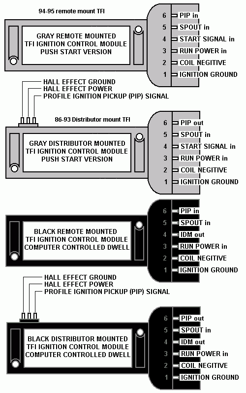
The TFI module mounted on the distributor is one of the culprits for a high speed miss on a warm engine. The other suspect is the PIP sensor inside the distributor. If the problem does not occur when the engine is cold, the TFI module or PIP is definitely suspect. Dumping the codes may help determine which one it is. You may need a special socket to remove the TFI module, but most auto parts stores will have one for $5-$7.
Be sure to use plenty of the heat sink grease on the new TFI and clean the old grease off the distributor.
See
Automotive Tools Specialty | Auto Mechanic & Technician Diagnostic, Testing Equipment | Thexton
diagram courtesy of Tmoss & Stang&2Birds