Progress Thread Out With The New - In With The Old

A little progress report. Pictured below is the 2" drum next to the original 1.5" and the two different sun gear shells. Since the new drum is obviously deeper, you also need to change the sun gear shell and sun gear (one piece actually).

There are options here. AOD has these gear ratios.
1st = 2.40
2nd = 1.47
3rd = 1
4th = .667. A few early AODE's also had these ratios.

4r70w has these ratios.

1st = 2.84
2nd = 1.55
3rd = 1
4th = .70

You can go with either ratio set on the AOD case build depending on how you combine various parts. If you want the AOD ratios and the 2" drum, you only need the 2" steel drum and a sun gear shell with 36 tooth sun gear (somewhat rare as it only came on the few early AODE's that had the 2.40 gearset).

The 4r70w uses a 38 tooth sun gear and that only works with the 4r70w ratios. If going with 4r70w ratios you basically need all the 4r70w internals except one part. You must still use the AOD output shaft. This is because the AOD uses a governor and it's shaft has the oil hole to supply it. 4r70w and AODE output shafts do not have this oil feed hole since they do not use a governor. They are electronically controlled instead.

I'm retaining the AOD 2.40 gearset in my build. Here are the drums and shells side by side. The shorter sun shell goes with the larger 2"drum. Luckily I found the used sun shell on Amazon for $39.
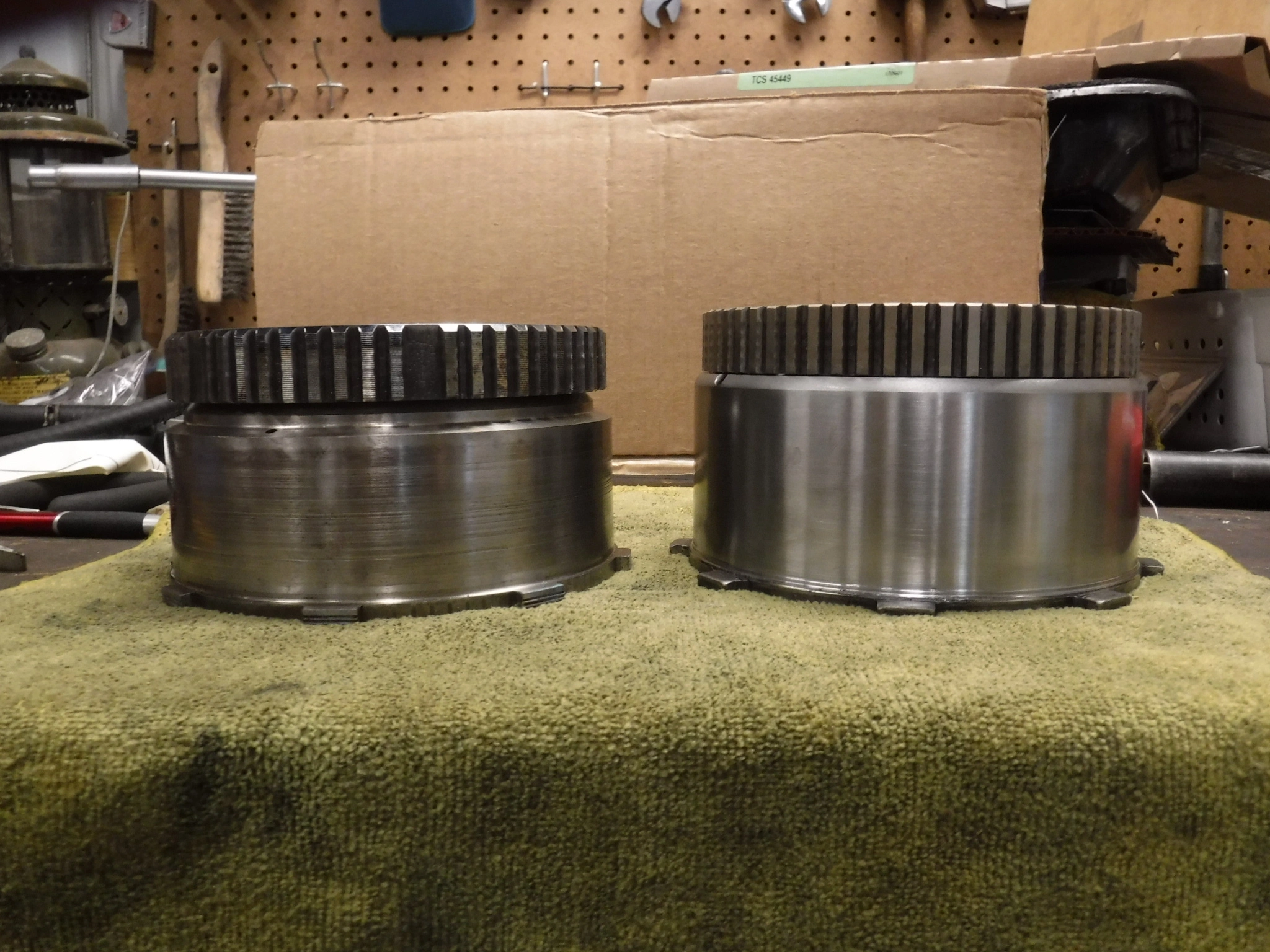
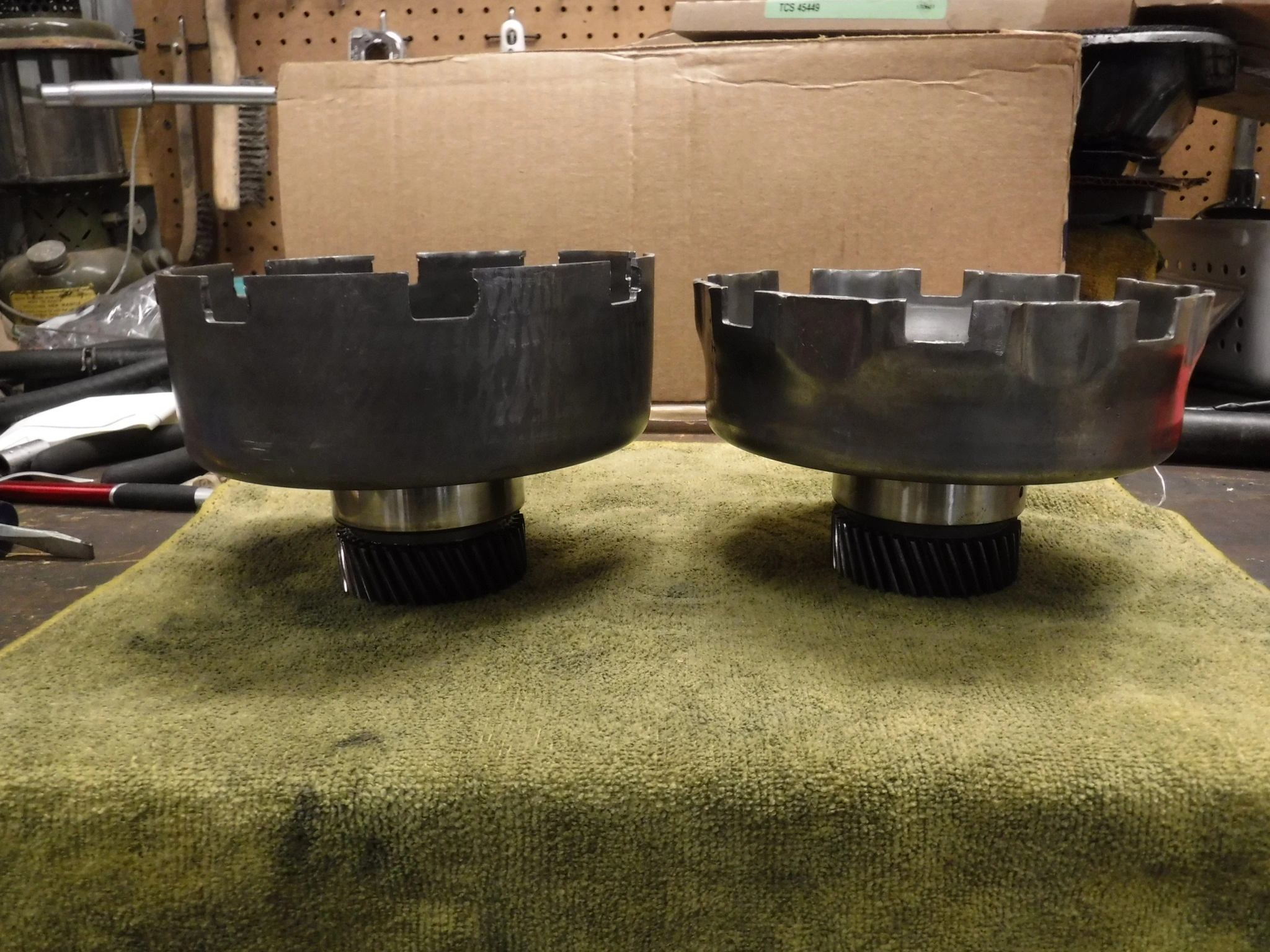
DSCF1749.webp

DSCF1750.webp
 
I've been working on the engine too. I made a positive stop tool to find true TDC on the harmonic balancer with heads installed. I used a spark plug, hollowed the guts, threaded the inside, screwed in a bolt and cut the bolt head off. This tool gets screwed into the #1 plug hole far enough that its stops the piston short of TDC. Turn crank gently clockwise until the piston hits and the crank stops. Mark the balancer. Turn crank gently counter clockwise until the piston hits and the crank stops. Mark the balancer again. True TDC is the point exactly half way between these two marks. In the case of this engine, the true TDC is 2 degrees different from the factory 0 mark. True TDC was actually at 2 degrees BTDC on the factory balancer mark. I penciled a mark there and installed timing tape lining up 0 on the tape with 2 degrees BTDC on the balancer.

DSCF1751.webp

DSCF1752.webp

DSCF1754.webp

DSCF1756.webp

DSCF1760.webp
 
I damaged 3 lips seals so far. The pump piston lip seal by having too much air in the compressor during an air test. Both inner and outer forward clutch piston lip seals by attempting makeshift methods without proper seal installation tool.

New lip seals and seal install kit on the way. $135
 
  • Like
Reactions: 90sickfox
As stated previously the car had no o2 sensors and has been running on some unknown tune chip in the ECU. I'm ditching that chip and reverting to stock tune. The exhaust pipe on the car is an H pipe, BBK I believe. It has bungs for the o2's. I sprayed them with PB Blaster a couple times over a few days. Luckily the bung plugs cooperated and came out with only a moderate effort. I'm really glad the plugs were female hex allen and deep.

Out with the bung plugs

DSCF1770.webp


In with the new Bosch o2's

DSCF1771.webp
 
Lets visit my valve spring decision again please. History > I have removed the x303 .542 lift cam and installed a stock HO cam .444 lift. The heads are GT40, non P. The heads have aftermarket dual springs / retainers on them but I dont know what the specs on them are. They have gold colored retainers and keepers. The keepers appear more beefy when compared to the stock ones. Any idea what kind of retainers / springs these might be? Could these be titanium retainers? The intake inner springs are flat wound and the exhaust inner springs are round wound.

I was going to change back to the stock springs but I'm not sure if I should. My concern is that these springs could be overkill in pressure for the stock cam. I'm happy to keep them as long as they don't cause problems. I have a source that can check the spring rates for me on a testing tool. What seat pressure and open pressures would be the maximum to not exceed for a stock cam application? Stock pushrods too.

I'll have the springs tested to see what the rates are and post back. But I wondered if anyone has any initial thoughts on keeping the dual springs with the stock cam.

IMG_1013.webp


IMG_1015.webp


IMG_0960.webp
 
On further looking I saw one of the aftermarket inner springs was actually broken. The installed height on the aftermarket springs was wrong too. At their installed height 1.90 the seat pressure was only 70lbs. The retainers are dished making the height too high. Furthermore the aftermarket springs are single with damper on the intakes and double on the exhausts. I got no clue whats going on with these but I'm yanking them. Thing now is I have to buy locater cups for the spring seat in the head. These guide bosses had been machined for a dual spring kit even though I dont think the kit installed even required it. So now, locater cups are needed to prevent the spring for excessive walking side to side on its seat.

The stock springs I have tested good at their correct installed height so they're going back in once I get the right locater cups. Closest match I can find is Comp Cams 4704-16. Ordering them now.

Here's a vid showing how the stock springs would walk on the machined heads without locater cups. BTW, the aftermarket kit had locaters but they were too large. Wrong for both the aftermarket and stock springs. Too big in diameter allowing too much walking space. The stock springs on un-machined E7 heads can walk about .030. I'll be sloppier than that at about .060 but that the best I can get it with available parts.

BTW, the intake springs on this setup had .150 walking space on their seats because their cups were too big. That's gotta be wrong isnt is?


View: https://youtu.be/Ae_oJ0FtUZE
 
Last edited:
Comp Cams 4704 spring locater cups were the right choice for this application of stock single HO valve springs installed on heads that were previously machined for dual springs. Here's a pic of how well they size up in the stock springs. Maybe .050 lateral movement at most. The center hole has less than .010 movement on the machined guide boss. Tolerable in my opinion.

IMG_1019.webp
 
IMG_1042.webp
Blows me away how idiotic people can be. I need a break.

Working on muffed up douch bag wiring tuck. Undoing it actually. If I could find these dick wads....I swear I would.....well, let's save that idea for the end of the world.

Pulling crap out from under the fender skirts and anywhere you can think of. Why? Just......Why

Picture sideways sorry
 
Meanwhile I got the trans back together and bolted up in the car. Waiting on reverse servo to finish valve body install. All that can happen with trans in car.

I'm feeling moderately confident. If i f'ed it up I promise I'll tell. We shall see.

I just am dying to get all the crap underneath done. That way I can lower it down and focus on the engine topside.
 
  • Like
Reactions: 90sickfox
IMG_1045.webp
No way to pull it all back when it belongs unless I unwrap all the tape. I can only hope nobody paid the douchbag that did this, .... to do this
 
I have no clue how they even got these relay plugs through the hole in the shock tower. They must have pulled the wiring out of the harness plug and fed it through, then put it back in the connector.

Who does this?
 
IMG_1051.webp
Ok, got more pics of perceived progress on the way. Multitasking is an understatement on this project.

Currently working on harness routing. Good thing is none of it appears to be cut up. It was just routed everywhere it shouldn't be.

Meanwhile, I'm figuring out what everything is. But this part has me stumped. It hangs from the harness in the area behind the driver side headlight, somewhere near the washer fluid bottle. Has 7 wires harness plug but doesn't appear to go anywhere. What is it?