93 5.0 5 speed I did a self test and these are the codes that came up ignition on 85,67,18,32,33,63,87,96 and these are ones came up running 12,94,44 put a A9l in about 5 years age ran fine up until about a year ago it would run ruff then run fine know it's surging idling ruff driving car you press pedal to floor losses all power rpm will stay around 1500 until you let off gas then picks up give it gas state
starts stalling losing power etc so I guess replace ecm thanks for any help before I drive it off a cliff or park on side of road and leave it lol
Most of you codes (85, 32, 33, 44, 94 ) are related to damaged or missing emissions equipment.
Removing the pollution control equipment from a 5.0 Mustang is a bad idea. All you have accomplished is to make the computer mad and spit codes. The pollution control equipment all shuts off at wide open throttle, so the HP losses from it on the car are 2-5 HP. The catalytic converters may soak a few more HP than that. None of the pollution control equipment reduces the HP enough to cost you a race in anything but professional drag strip competition. I seriously doubt that you will be in the final runoff on “Pinks”, so leave the smog equipment in place and make sure it is working correctly.
Know what does what
before removing it. Remove or disable the wrong thing and the computer sets the check engine light and runs in "limp mode". Limp mode means reduced power and fuel economy.
If you removed the smog pump and still have catalytic converters, they will ultimately clog and fail.
Here's a book that will get you started with how the Ford electronic engine control or "computer" works.
Ford Fuel Injection & Electronic Engine Control 1988-1993 by James Probst :ISBN 0-8376-0301-3.
It's about $20-$45 from Borders.com see
http://www.amazon.com/ . Select books and then select search. Use the ISBN number (without dashes or spaces) to do a search
Use the ISBN number and your local library can get you a loaner copy for free. Only thing is you are limited to keeping the book for two weeks. It is very good, and I found it to be very helpful.
Remove any of the equipment and you will not pass a full smog check, cannot title the car in an area that does smog checks and have broken several federal laws. Granted that the Feds are short on people to check cars, but it is still Federal law.
"Why should I leave the smog equipment on if I live in an area that doesn't do smog inspections?"
What's good sauce for the goose is good sauce for the gander. I lived in Florida and had two smog pumps fail on two different 89 5.0 Mustangs. I replaced both of them, even though there was no emissions inspection. Why?
1.) It a federal law that requires emissions equipment to be in place and functional. I have no intention of breaking a law designed to protect my general health and wellbeing, even if I don't like it. I have respect for the rights and wellbeing of other people, and am not one of those whose nature is rebellion.
2.) Whatever imaginary "improvements" someone may strive for, there is very little evidence that the results of removing emissions results in a better car. I can achieve excellent results in performance with all the smog equipment in place and working properly. Maybe you can't, but that is no excuse for removing the emissions equipment. Look at the new 5.0 Mustangs – 281 cubic inches and 420+ flywheel HP with full emissions equipment with no aftermarket parts. That tells me that it is possible on a mass production car. It also shows that the guys that designed the engine knew what they were doing to achieve that goal.
3.) I like to breathe clean air, and working emissions equipment helps me do my part to make that possible. Los Angeles has breathable air even with millions of cars: Beijing, the capitol of China has some of the worst air in the world. Why – no emissions requirements for cars.
I don’t want to live where the air looks like this…
See
http://www.taipeitimes.com/News/feat/archives/2014/01/15/2003581312
Go back and read the first two posts if you haven't already done so; that's where all the fixes are.
Codes 12, 18 and 63 are non emissions related and since some bonehead removed the emissions equipment, they are the ones you need to fix first.
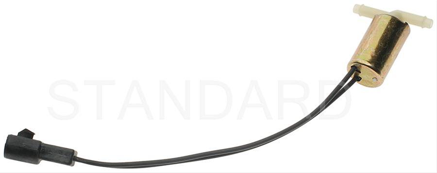
Code 85 CANP solenoid - The Carbon Canister solenoid is inoperative or missing.
Revised 11 –Jan_2015 to add warning about vacuum leaks due to deteriorated hose or missing caps on vacuum lines when the solenoid is removed.
Check vacuum lines for leaks and cracks. Check electrical wiring for loose connections, damaged wiring and insulation. Check solenoid valve operation by grounding the gray/yellow wire to the solenoid and blowing through it.
The computer provides the ground for the solenoid. The red wire to the solenoid is always energized any time the ignition switch is in the run position.
If you disconnected the carbon canister and failed to properly cap the vacuum line coming from under the upper intake manifold, you will have problems. You will also have problems if the remaining hose coming from under the upper intake manifold or caps for the vacuum line are sucking air.
Charcoal canister plumbing - one 3/8" tube from the bottom of the upper manifold to the rubber hose. Rubber hose connects to one side of the canister solenoid valve. Other side of the solenoid valve connects to one side of the canister. The other side of the canister connects to a rubber hose that connects to a line that goes all the way back to the gas tank. There is an electrical connector coming from the passenger side injector harness near #1 injector that plugs into the canister solenoid valve. It's purpose is to vent the gas tank. The solenoid valve opens at cruse to provide some extra fuel. The canister is normally mounted on the passenger side frame rail near the smog pump pulley.
Connecting the gas tank vent line directly to the intake manifold will result in fuel vapor being constantly sucked into the intake manifold. There is unmetered fuel that the computer cannot adjust for. The result is poor idle and poor fuel economy.
It does not weigh but a pound or so and helps richen up the cruse mixture. It draws no HP & keeps the car from smelling like gasoline in a closed garage. So with all these good things and no bad ones, why not hook it up & use it?
The purge valve solenoid connector is a dangling wire that is near the ECT sensor and oil filler on the passenger side rocker cover. The actual solenoid valve is down next to the carbon canister. There is about 12"-16" of wire that runs parallel to the canister vent hose that comes off the bottom side of the upper intake manifold. That hose connects one port of the solenoid valve; the other port connects to the carbon canister.
The purge valve solenoid should be available at your local auto parts store.
Purge valve solenoid:
The carbon canister is normally mounted on the passenger side frame rail near the smog pump pulley.
Carbon Canister:
Code 67
Revised 18-Mar-2017 to include warning about the necessity of having a 5 speed O2 Sensor wiring harness when bypassing the wiring for test purposes
Cause of problem:
Clutch not depressed (5 speed) or car not in neutral (5 speed and auto) or not in park (auto) or A/C in On position when codes where dumped. Possible neutral safety switch or wiring problem. This code will prevent you from running the Key On Engine On tests.
External evidence from other sources claims that a code 67 can cause an idle surge condition. Do try to find and fix any issues with the switch and wiring if you get a code 67.
What the NSS (Neutral Safety Switch) does:
5 speed transmission: It has no connection with the starter, and the engine can be cranked without it being connected.
Auto transmission: It is the safety interlock that prevents the starter from cranking the engine with the transmission in gear.
What it does for both 5 speed and auto transmission cars:
The computer wants to make sure the A/C is off due to the added load on the engine for the engine running computer diagnostic tests. It also checks to see that the transmission is in Neutral (5 speed and auto transmission) and the clutch depressed (T5, T56, Tremec 3550 & TKO)). This prevents the diagnostics from being run when the car is driven. Key On Engine Running test mode takes the throttle control away from the driver for several tests.
This could prove hazardous if the computer was jumpered into test mode and then driven.
The following is for 5 speed cars only. Do not do this unless you are sure that you have a 5 speed O2 Sensor harness!!!! Smoke, sparks and expensive pain in the wallet may ensue if you don’t.
The NSS code 67 can be bypassed for testing. You will need to temporarily ground computer pin 30 to the chassis. Computer pin 30 uses a Lt blue/yellow wire. Remove the passenger side kick panel and then remove the plastic cover from the computer wiring connector. Use a safety pin to probe the connector from the rear. Jumper the safety pin to the ground near the computer.
Be sure to remove the jumper BEFORE attempting to drive the car!!!
Code 18 - SPOUT out or wiring fault - look for short to ground in SPOUT wiring going
back to the computer. Possible bad TFI or defective 22 K resistor in the IDM wiring
Use a timing light to check the timing: remove the SPOUT and observe that the timing retards at least 4 degrees. Put the SPOUT back in place and observe that the spark advances at least 4 degrees.
This code can disable spark advance and reduce power and fuel economy.
Remove the passenger side kick panel and disconnect the computer connector.
There is a 10 MM bolt that holds it in place.
Disconnect the TFI module connector from the TFI and the measure the resistance between the yellow/lt green wire and ground.
You should see greater than 100 K (100000) ohms.
Check the resistance from Pin 4 on the computer connector (dark green/yellow) and the dark green/yellow wire on the TFI connector. You should see 20-24 K Ohms (20,000-24,0000 ohms).
Resistor location: A big thanks to liljoe07 for this information:
Check over by the brake booster. Its not in the harness on the TFI, its on the main part of the harness over by the plugs that connect to the dash harness. About 6" or so from that, going back toward the EEC.
If I remember right, the resistor is covered in a shrink tubing that is sealed to the wires. So, you wont be able see any markings. The shrink tubing is labeled though. It's a 22kohm 1/2 watt resistor.
Here is the location.
Next measure the resistance between the yellow/lt green wire on the TFI module connector and Pin 36 on the computer connector. With the SPOUT plug in place, you should see less than 2 ohms.
The following is a view from the computer side of the computer connector.
This diagram is the wire side of the computer connector.
Diagram courtesy of Tmoss & Stang&2birds
Code 32 - Code 32 – EGR voltage below closed limit
Missing VREF (5v), 10 pin connector problems, EGR wiring connector problems
Let’s put on our Inspector Gadget propeller head beanies and think about how this works:
The EGR sensor is a variable resistor with ground on one leg and Vref (5 volts) on the other. Its’ resistance ranges from 4000 to 5500 Ohms measured between Vref & ground, depending on the sensor. The center connection of the variable resistor is the slider that moves in response to the amount of vacuum applied. The slider has some minimum value of resistance greater than 100 ohms so that the computer always sees a voltage present at its’ input. If the value was 0 ohms, there would be no voltage output. Then the computer would not be able to distinguish between a properly functioning sensor and one that had a broken wire or bad connection. The EGR I have in hand reads 700 Ohms between the slider (EPV) and ground (SIG RTN) at rest with no vacuum applied.
As vacuum is applied, the voltage on the slider increases (EVP). As the voltage increases, the computer knows the how much the EGR valve is opened and how much exhaust gas is being recirculated. It uses the load table to calculate the amount of exhaust gas required depending on RPM, Mass Air Flow, ACT, ECT & TPS. It then sends a signal to the Electronic Vacuum Regulator to hold, increase or decrease the vacuum being applied to the EGR valve.
Theory class is over now, let’s spin up our propeller head beanies and get with it… Go Gadget, Go…
Measure the resistance of the EGR sensor between the two end pins. You should see between 3500 to 5500 Ohms. With the sensor removed, measure the resistance again while pressing on the plunger. You should see the resistance drop from its high value to a low reading of 200-700 ohms depending on the sensor. No resistance readings, or values way out of range, the sensor is bad.
If the Orange white wire has Vref, (5 volts =/-.25 volt) then you have some wiring problems because the computer isn’t seeing the minimum voltage on the EVR pin. Ohm the wiring back to the computer. Check for resistance between the brown/lt green wire on the EGR sensor and pin 27 on the computer: you should have less than 1 ohm. Repeat the process for the orange/white wire and pin 26. Do it again between the black/white wire and pin 46. In no case should you have more than 1 ohm. Remember that resistance checks are always done with the power off the circuit.
See the graphic for the 10 pin connector circuit layout.
Voltage and resistance checks are good: Here’s an EGR test procedure I copied from cjones
to check the EGR valve:
bring the engine to normal temp.
connect a vacuum pump to the EGR Valve
apply 5 in vacuum to the valve.
if engine stumbled or died then EGR Valve and passage(there is a passageway through the heads and intake) are good.
if engine did NOT stumble or die then either the EGR Valve is bad and/or the passage is blocked.
if engine stumbled, connect vacuum gauge to the hose coming off of the EGR Valve
snap throttle to 2500 RPM’s (remember snap the throttle don't hold it there).
did the vacuum gauge show about 5 in vacuum?
if not, check for manifold vacuum at the EGR vacuum valve.
if you have manifold vacuum then connect vacuum gauge to the EGR valve side of the vacuum valve and snap throttle to 2500 RPM’s.
should read about 5 in vacuum
End of cjones's test.
If the test procedure fails to provide proper vacuum, check vacuum feed lines for cracks & damage. If the vacuum lines are good, check the electrical wiring to the EVR. If the EVR electrical wiring is good, look for 12 volts on the red wire for the EVR. If the 12 volts is good, look for a varying voltage on the dark green wire on the EVR. Case of last resort, replace the EVR and then the computer
Code 33 - Insufficient EGR flow detected.
Look for vacuum leaks, cracked vacuum lines, failed EGR vacuum regulator. Check to see if you have 10” of vacuum at the EGR vacuum connection coming from the intake manifold. Look for electrical signal at the vacuum regulator solenoid valves located on the rear of the passenger side wheel well. Using a test light across the electrical connector, it should flicker as the electrical signal changes. Remember that the computer does not source any power, but provides the ground necessary to complete the circuit. That means one side of the circuit will always be hot, and the other side will go to ground or below 1 volt as the computer switches on that circuit.
Check for resistance between the brown/lt green wire on the EGR sensor and pin 27 on the computer: you should have less than 1.5 ohm.
Backside view of the computer wiring connector:
See the following website for some help from Tmoss (diagram designer) & Stang&2Birds (website host)
http://www.veryuseful.com/mustang/tech/engine/images/fuel-alt-links-ign-ac.gif
http://www.veryuseful.com/mustang/tech/engine/images/88-91eecPinout.gif
EGR test procedure courtesy of cjones
to check the EGR valve:
bring the engine to normal temp.
connect a vacuum pump to the EGR Valve or
see the EGR test jig drawing below. Connect the test jig or to directly to manifold vacuum.
Do not connect the EGR test jig to the EVR (Electronic Vacuum Regulator).
apply 5in vacuum to the valve.
Using the test jig, use your finger to vary the vacuum
if engine stumbled or died then EGR Valve and passage(there is a passageway through the heads and intake) are good.
if engine did NOT stumble or die then either the EGR Valve is bad and/or the passage is blocked.
if engine stumbled,
connect EGR test jig to the hose coming off of the EGR Valve.
Use your finger to cap the open port on the vacuum tee.
snap throttle to 2500 RPM (remember snap the throttle don't hold it there).
did the vacuum gauge show about 2-5 in vacuum?
if not the EVR has failed
EGR test jig
The operation of the EGR vacuum regulator can be checked by using a test light applied across the wiring connector. Jumper the computer into self test mode and turn the key on but do not start the engine. You will hear all the actuators (including the EVR vacuum regulator) cycle. Watch for the light to flicker: that means the computer has signaled the EGR vacuum regulator successfully.
Code 63 - Throttle Position Sensor (TPS) signal too low.
Revised 02-Jul-2009 to update TPS setting procedure & add 10 pin connector layout.
Vref missing (5 volt reference voltage supplied by the computer), bad connections or damaged wiring, TPS sensor failed, TPS sensor way out of adjustment. Use a DVM to check for 5 volts on the Orange wire. If it is missing, look for +5 volts at the Orange wire on the EGR or MAP/Baro sensor located on the firewall near the center of the car. If there is +5 volts on the MAP/Baro sensor, but not on the EGR, clean the #2 & #5 pin on the white 10 pin connector. If there is +5 volts on the EGR but not on the TPS, look for bad wiring inside the engine fuel injector harness.
See the graphic for the 10 pin connector circuit layout.
Setting the TPS voltage
You'll need a Digital Voltmeter (DVM) to do the job.
Wire colors & functions:
Orange/white = 5 volt VREF from the computer
Dark Green/lt green = TPS output to computer
Black/white = Signal ground from computer
Always use the Dark Green/lt green & Black/white wires to set the TPS base voltage.
Do the test with the ignition switch in the Run position without the engine running.
Use the Orange/white & Black white wires to verify the TPS has the correct 5 volts source from the computer.
Setting the TPS: you'll need a good Digital Voltmeter (DVM) to do the job. Set the TPS voltage at .5- 1.1 range. Because of the variables involved with the tolerances of both computer and DVM, I would shoot for somewhere between .6 and 1.0 volts. Unless you have a Fluke or other high grade DVM, the second digit past the decimal point on cheap DVM’s is probably fantasy.
Since the computer zeros out the TPS voltage every time it powers up, playing with the settings isn't an effective aid to performance or drivability. The main purpose of checking the TPS is to make sure it isn't way out of range and causing problems.
The Orange/White wire is the VREF 5 volts from the computer. You use the Dark Green/Lt green wire (TPS signal) and the Black/White wire (TPS ground) to set the TPS. Use a pair of safety pins to probe the TPS connector from the rear of the connector. You may find it a little difficult to make a good connection, but keep trying. Put the safety pins in the Dark Green/Lt green wire and Black/White wire. Make sure the ignition switch is in the Run position but the engine isn't running.
Always adjust the TPS and Idle with the engine at operating temp. Dive it around for a bit if you can and get it nice and warm.
When you probe the leads of the TPS, do not use an engine ground, put the ground probe into the lead of the TPS. You should be connecting both meter probes to the TPS and not one to the TPS and the other to ground.
The TPS is a variable resistor, much like the volume control knob on a cheap radio. We have all heard them crackle and pop when the volume is adjusted. The TPS sensor has the same problem: wear on the resistor element makes places that create electrical noise. This electrical noise confuses the computer, because it expects to see a smooth increase or decrease as the throttle is opened or closed.
TPS testing: most of the time a failed TPS will set code 23 or 63, but not always. Use either an analog meter or a DVM with an analog bar graph and connect the leads as instructed above. Turn the ignition switch to the Run position, but do not start the engine. Note the voltage with the throttle closed. Slowly open the throttle and watch the voltage increase smoothly, slowly close the throttle and watch the voltage decrease smoothly. If the voltage jumps around and isn’t smooth, the TPS has some worn places in the resistor element. When the throttle is closed, make sure that the voltage is the same as what it was when you started. If it varies more than 10%, the TPS is suspect of being worn in the idle range of its travel.
Code 87 – fuel pump primary circuit failure. The fuel pump lost power while the engine was running. Check fuel pump relay, check inertia switch, wiring to/from inertia switch, red wire going to inertia switch for +12volts. Check the other side of inertia switch for +12 volts.
Diagram of the fuel pump wiring for 86-90 cars
Diagram of the fuel pump wiring for 91-93 cars.
Code 96 causes & tests 91-93 models. – KOEO- Fuel pump monitor circuit shows no power - Fuel pump relay or battery power feed was open - Power / Fuel Pump Circuits. The fuel pump circuit lost power at one time or another.
Revised 24-Mar-2017 to add text about the A/C Wide Open Throttle relay and using the wire colors to identify which relay is the fuel pump relay
Clear the codes by disconnecting the battery and turning on the headlights for about 5 minutes before reconnecting the battery. This will clear any remaining codes. Drive the car for several days and dump the codes again. In many cases, this clears the 96 code.
Look for a failing fuel pump relay, bad connections or broken wiring. On 91 model cars, the fuel pump relay is under the driver’s seat. The fuel pump relay is located under the Mass Air Meter on Fox bodied stangs built after 91. It can be confused with the A/C Wide Open Throttle relay which is in the same area. Use the wire colors as shown in the diagram below to identify which relay is the fuel pump relay.
Diagram of the fuel pump wiring for 91-93 cars.
Look for power at the fuel pump - the fuel pump has a connector at the rear of the car with a pink/black wire and a black wire that goes to the fuel pump. The pink/black wire should be hot when the test connector is jumpered to the test position. To trick the fuel pump into running, find the ECC test connector and jump the connector in the lower RH corner to ground. No voltage when jumpered, check the fuel pump relay and fuse links.
Power feed: Look for 12 volts at the pink/black wire (power source for fuel pump relay). No voltage or low voltage, bad fuse link, bad wiring, or connections. Remember that on 92 or later models the fuel pump relay is located under the Mass Air meter. Watch out for the WOT A/C control relay on these cars, as it is located in the same place and can easily be mistaken for the fuel pump relay.
Relay: Turn on the key and jumper the ECC test connector as previously described. Look for 12 volts at the dark green\yellow wire (relay controlled power for the fuel pump). No voltage there means that the relay has failed, or there is a broken wire in the relay control circuit.
Be sure to closely check the condition of the relay, wiring & socket for corrosion and damage.
91-93 Models:
Using the diagram, check the dark green/yellow wire from the fuel pump relay: you should see 12 volts or so. If not the relay has failed or is intermittent. Check the inertia switch: on a hatch it is on the driver’s side by the taillight. Look for a black rubber plug that pops out: if you don't find it, then loosen up the plastic trim. Check for voltage on both sides of the switch. If there is voltage on both sides, then check the Pink/black wire on the fuel pump relay: it is the power feed to the fuel pump. Good voltage there, then the fuel pump is the likely culprit since it is getting power. No voltage there, check the Pink/black wire, it is the power feed to the fuel pump relay & has a fuse link in it. Good voltage there & at the dark green/yellow wire, swap the relay.
All testing is done with the ignition switch in the Run position. Do not forget this crucial step.
The pink/black wire should have the same voltage as the battery positive terminal +/- 0.25 volt. If not, then the fuse link for the fuel pump has opened up.
With the test jumper in place the green/yellow wire should be the same voltage as the pink/black wire +/- 0.25 volt.
If not, look at the red wire: should have the same voltage as the battery positive terminal +/- 0.25 volt.
If not, then check the yellow wire on the EEC relay located on top of the computer. This one is hard to get to. It should have the same voltage as the battery positive terminal +/- 0.25 volt. If not, then the fuse link for the computer has opened up.
If the red wire does not have the same voltage as the battery positive terminal +/- 0.25 volt and the yellow wire on the EEC relay does, then check the red/green wire on the EEC relay. It should have the same voltage as the battery positive terminal +/- 0.25 volt. If not, then the ignition switch is defective or the fuse link in the ignition wiring harness has opened up, or the EEC relay is defective.
All testing is done with the ignition switch in the Run position. Do not forget this crucial step.
The pink/black wire s should have the same voltage as the battery positive terminal +/- 0.25 volt. If not, then the fuse link for the fuel pump has opened up.
With the test jumper in place the green/yellow wire should be the same voltage as the pink/black wire +/- 0.25 volt.
If not, look at the red wire: should have the same voltage as the battery positive terminal +/- 0.25 volt.
If not, then check the yellow wire on the EEC relay located on top of the computer. This one is hard to get to. It should have the same voltage as the battery positive terminal +/- 0.25 volt. If not, then the fuse link for the computer has opened up.
If the red wire does not have the same voltage as the battery positive terminal +/- 0.25 volt and the yellow wire on the EEC relay does, then check the red/green wire on the EEC relay. It should have the same voltage as the battery positive terminal +/- 0.25 volt. If not, then the ignition switch is defective or the fuse link in the ignition wiring harness has opened up, or the EEC relay is defective.
Diagram courtesy of Tmoss & Stang&2birds
Code 12 -Idle Air Bypass motor not controlling idle properly (generally idle too low) - IAB dirty or not working. Clean the electrical contacts with non flammable brake parts cleaner at the same time.
IAC doesn't work: look for +12 volts at the IAC red wire. Then check for continuity between the white/lt blue wire and pin 21 on the computer. The IAC connector contacts will sometimes corrode and make the IAC not work. The red wire on the IAC is always hot with the engine in run mode. The computer provides a ground for the current for the IAC. It switches the ground on and off, making a square wave with a varying duty cycle. A normal square wave would be on for 50% of the time and off for 50% of the time. When the idle speed is low, the duty cycle increases more than 50% to open the IAC more. When the engine speed is high, it decreases the duty cycle to less than 50% to close the IAC. An old-fashioned dwell meter can be used to check the change: I haven’t tried it personally, but it should work. In theory, it should read ½ scale of whatever range you set it on with a 50% duty cycle. An Oscilloscope is even better if you can find someone who has one and will help.

Recommended procedure for cleaning the IAC/IAB:
Conventional cleaning methods like throttle body cleaner aren’t very effective. The best method is a soak type cleaner used for carburetors. If you are into fixing motorcycles, jet skis, snowmobiles or anything else with a small carburetor, you probably have used the one gallon soak cleaners like Gunk or Berryman. One of the two should be available at your local auto parts store for $22-$29. Take the solenoid off the body and set it aside: the carb cleaner will damage some types of plastic parts. Soak the metal body in the carb cleaner overnight. There is a basket to set the parts in while they are soaking. When you finish soaking overnight, twist the stem of the IAB/IAC that sticks out while the blocker valve is seated. This removes any leftover deposits from the blocker valve seat. Rinse the part off with water and blow it dry with compressed air. The IAC/IAB should seal up nicely now. Once it has dried, try blowing through the bottom hole and it should block the air flow. Reassemble and reinstall to check it out.
Gunk Dip type carb & parts soaker:
Setting the base idle speed:
First of all, the idle needs to be adjusted to where the speed is at or below 600 RPM with the IAC disconnected. If you have a wild cam, you may have to raise this figure 100-150 RPM or so. Then the electrical signal through the IAC can vary the airflow through it under computer control. Remember that the IAC can only add air to increase the base idle speed set by the mechanical adjustment. The 600 RPM base idle speed is what you have after the mechanical adjustment. The IAC increases that speed by supplying more air under computer control to raise the RPM’s to 650-725 RPM’s. This figure will increase if you have a wild cam, and may end up between 800-950 RPM
Remember that changing the mechanical idle speed adjustment changes the TPS setting too.
This isn't the method Ford uses, but it does work. Do not attempt to set the idle speed until you have fixed all the codes and are sure that there are no vacuum leaks.
Disconnect the battery negative terminal and turn the headlights on. Leave the battery negative terminal disconnected for 5 minutes or so. Then turn the headlights off and reconnect the battery. This erases the computer settings that may affect idle performance.
Warm the engine up to operating temperature, place the transmission in neutral, and set the parking brake. Turn off lights, A/C, all unnecessary electrical loads. Disconnect the IAC electrical connector. Remove the SPOUT plug. This will lock the ignition timing so that the computer won't change the spark advance, which changes the idle speed. Note the engine RPM: use the mechanical adjustment screw under the throttle body to raise or lower the RPM until you get the 600 RPM mark +/- 25 RPM. A wild cam may make it necessary to increase the 600 RPM figure to 700 RPM or possibly a little more to get a stable idle speed.
Changing the mechanical adjustment changes the TPS, so you will need to set it.
When you are satisfied with the results, turn off the engine, and re-install the SPOUT and reconnect the IAC. The engine should idle with the range of 650-750 RPM without the A/C on or extra electrical loads. A wild cam may make this figure somewhat higher.
An engine that whose idle speed cannot be set at 600 RPM with the IAC disconnected has mechanical problems. Vacuum leaks are the #1 suspect in this case. A vacuum gauge will help pinpoint both vacuum leaks and improperly adjusted valves. A sticking valve or one adjusted too tight will cause low vacuum and a 5"-8" sweep every time the bad cylinder comes up on compression stroke. An extreme cam can make the 600 RPM set point difficult to set. Contact your cam supplier or manufacturer to get information on idle speed and quality
Codes 44 & 94 - AIR system inoperative - Air Injection. Check vacuum lines for leaks, & cracks. Check for a clogged air crossover tube, where one or both sides of the tube clog with carbon.
Revised 21 Sep 2012 to correct the description of the process that sets the code and include Thermactor Air System diagram.
If you have a catalytic converter H pipe, you need to fix these codes. If you don't, then don't worry about them.
Code 44 passenger side air not functioning.
Code 94 driver side air not functioning.
The TAD solenoid/TAD diverter valve directs smog pump output to either the crossover tube attached to the cylinder heads or to the catalytic converters.
The O2 sensors are placed before the catalytic converters, so they do not see the extra O2 when the smog pump's output is directed to the converters or the input just before the converter.
The 44/94 code uses the O2 sensors to detect a shift in the O2 level in the exhaust. The smog pump provides extra air to the exhaust which raises the O2 level in the exhaust when the smog pump output is directed through the crossover tube.
When there is an absence of increase in the O2 levels when the TAD solenoid/TAD diverter valve directs air through the crossover tube, it detects the lower O2 level and sets the code.
Failure mode is usually due to a clogged air crossover tube, where one or both sides of the tube clog with carbon. The air crossover tube mounts on the back of the cylinder heads and supplies air to each of the Thermactor air passages cast into the cylinder heads. When the heads do not get the proper air delivery, they set codes 44 & 94, depending on which passage is clogged. It is possible to get both 44 & 94, which would suggest that the air pump or control valves are not working correctly, or the crossover tube is full of carbon or missing.
Testing the system:
Note that the engine must be running to do the tests unless stated otherwise. For safety’s sake, do test preparation like loosening clamps, disconnecting hoses and connecting things to a vacuum source with the engine off.
Disconnect the big hose from smog pump: with the engine running you should feel air output. Reconnect the smog pump hose & apply vacuum to the first vacuum controlled valve: Its purpose is to either dump the pump's output to the atmosphere or pass it to the next valve.
The next vacuum controlled valve directs the air to either the cylinder heads when the engine is cold or to the catalytic converter when the engine is warm. Disconnect the big hoses from the back side of the vacuum controlled valve and start the engine. Apply vacuum to the valve and see if the airflow changes from one hose to the next.
The two electrical controlled vacuum valves mounted on the rear of the passenger side wheel well turn the vacuum on & off under computer control. Check to see that both valves have +12 volts on the red wire. Then ground the white/red wire and the first solenoid should open and pass vacuum. Do the same thing to the light green/black wire on the second solenoid and it should open and pass vacuum.
Remember that the computer does not source power for any actuator or relay, but provides the ground necessary to complete the circuit. That means one side of the circuit will always be hot, and the other side will go to ground or below 1 volt as the computer switches on that circuit.
The following computer tests are done with the engine not running.
The computer provides the ground to complete the circuit to power the solenoid valve that turns the
vacuum on or off. The computer is located under the passenger side kick panel. Remove the kick panel & the cover over the computer wiring connector pins. Check Pin 38 Solenoid valve #1 that provides vacuum to the first Thermactor control valve for a switch from 12-14 volts to 1 volt or less. Do the same with pin 32 solenoid valve #2 that provides vacuum to the second Thermactor control valve. Turning the ignition to Run with the computer jumpered to self-test mode will cause all the actuators to toggle on and off. If after doing this and you see no switching of the voltage on and off, you can start testing the wiring for shorts to ground and broken wiring. An Ohm check to ground with the computer connector disconnected & the solenoid valves disconnected should show open circuit between the pin 32 and ground and again on pin 38 and ground. In like manner, there should be less than 1 ohm between pin 32 and solenoid valve #2 and pin 38 & Solenoid valve #1.
The following computer tests are done with the engine running.
If after checking the resistance of the wiring & you are sure that there are no wiring faults, start looking at the solenoid valves. If you disconnect them, you can jumper power & ground to them to verify operation with the engine running. Power & ground supplied should turn on the vacuum flow, remove either one and the vacuum should stop flowing.
Typical resistance of the solenoid valves is in the range of 20-70 Ohms.
See the following website for some help from Tmoss (diagram designer) & Stang&2Birds (website host)
http://www.veryuseful.com/mustang/tech/engine/images/fuel-alt-links-ign-ac.gif
http://www.veryuseful.com/mustang/tech/engine/images/88-91eecPinout.gif
If you have a catalytic converter H pipe, you need to fix these codes. If you don't, then don't worry about them

") you will notice in the video around the 20sec mark the idle drops massively when i put it in gear then shoots back up when i put it back in park. any ideas what's causing this? i checked all the vacuum lines and nothing is leaking from what I can tell. I've gone through the checklist i'm at a loss this problem has been plaguing me for nearly a year!
you will notice in the video around the 20sec mark the idle drops massively when i put it in gear then shoots back up when i put it back in park. any ideas what's causing this? i checked all the vacuum lines and nothing is leaking from what I can tell. I've gone through the checklist i'm at a loss this problem has been plaguing me for nearly a year!