I will check for vacuum leaks as well but it' not idling that high anymore . I dumped the codes and got these
22: MAP out of range
63 :TPS
54 : ACT
I tried testing the TPS on the green wire but the highest it was reading was .035 V so idk if its defective or I wasn't getting a good read on it , gonna try again tomorrow
MAP/BARO sensor operation and code 22
Revised 14-Nov-2014 to add wire colors for frequency & voltage testing and engine sensor wiring diagrams.
On a Speed Density car, the MAP/BARO sensor is connected to the intake manifold and acts to sense the manifold pressure. Lower vacuum inside the intake manifold when combined with more throttle opening measured by the TPS means more airflow through the engine. As airflow increases, fuel flow through the injectors needs to increase to keep the air/fuel ratio where it needs to be. When manifold vacuum increases, the engine is either decelerating or idling, and it needs to reduce the fuel flow through the injectors.
On a Mass Air car, the MAP/BARO sensor vents to open air and actually senses the barometric pressure due to changes in weather and altitude. Its purpose is to set a baseline for the computer to know the barometric pressure. As barometric pressure decreases, it leans out the fuel flow to compensate for less oxygen in the air. When the barometric pressure rises, it increases to add fuel since there is more oxygen in the air. The fuel requirements decrease as altitude increases, since the atmospheric pressure decreases.
Disconnecting the MAP or BARO sensor will set code 22.
Misconnecting the BARO sensor to vacuum on a Mass Air car will cause the computer to lean out the fuel mixture.
Code 22 or 126 MAP (vacuum) or BARO signal out of range. The MAP or BARO sensor is pretty much the same sensor for both Mass Air & Speed Density cars. The main difference is where it is connected. Mass Air cars vent it to the atmosphere, while Speed Density cars connect it to the intake manifold vacuum. Its purpose is to help set a baseline for the air/fuel mixture by sensing changes in barometric pressure. The MAP or BAP sensor puts out a 5 volt square wave that changes frequency with variations in atmospheric pressure. The base is 154 HZ at 29.92" of mercury - dry sunny day at sea level, about 68-72 degrees. You need an oscilloscope or frequency meter to measure it. There a very few DVM’s with a price tag under $40 that will measure frequency, but there are some out there.
Map sensor wiring:
black/white - ground
orange/white or +5 volts power
white/red signal out.
Measure the +5 volt supply using the orange/white and black/white wires
Measure the signal using the black/white and white/red wires.
The MAP/BARO sensor is mounted on the firewall behind the upper manifold on 86-93 Mustangs.
Baro or MAP test using a real frequency meter - run the test key on, engine off. The noise from the ignition system will likely upset the frequency meter. I used a 10 x oscilloscope probe connected from the frequency meter to the MAP/BAP to reduce the jitter in the meter's readout. And oscilloscope is very useful if you have access to one or know of someone who does. With an oscilloscope, you can see the waveform and amplitude.
If it is defective, your air/fuel ratio will be off and the car’s performance & emissions will suffer
Some basic checks you can make to be sure that the sensor is getting power & ground:
Note that all resistance tests must be done with power off. Measuring resistance with a circuit powered on will give false readings and possibly damage the meter.
Check the resistance between the black/white wire on the MAP/BARO sensor and then the black/white wire on the EGR and the same wire on the TPS. It should be less than 1 ohm. Next check the resistance between the black/white wire and the negative battery cable. It should be less than 1.5 ohm.
The following power on check requires you to turn the ignition switch to the Run position.
Use a DVM to check for 5 volts on the orange/white wire. If it is missing, look for +5 volts at the orange/white wire on the TPS or EGR sensors. Use the black/white wire for the ground for the DVM.
Diagrams courtesy of Tmoss & Stang&2birds
Complete computer, actuator & sensor wiring diagram for 88-91 Mass Air Mustangs
Complete computer, actuator & sensor wiring diagram for 91-93 Mass Air Mustangs
See the following website for some help from Tmoss (diagram designer) & Stang&2Birds (website host) for help on 88-95 wiring
http://www.veryuseful.com/mustang/tech/engine/ Everyone should bookmark this site.
Complete computer, actuator & sensor wiring diagram for 91-93 Mass Air Mustangs
http://www.veryuseful.com/mustang/tech/engine/images/91-93_5.0_EEC_Wiring_Diagram.gif
Complete computer, actuator & sensor wiring diagram for 88-91 Mass Air Mustangs
http://www.veryuseful.com/mustang/tech/engine/images/88-91_5.0_EEC_Wiring_Diagram.gif
Ignition switch wiring
http://www.veryuseful.com/mustang/tech/engine/images/IgnitionSwitchWiring.gif
Fuel, alternator, A/C and ignition wiring
http://www.veryuseful.com/mustang/tech/engine/images/fuel-alt-links-ign-ac.gif
O2 sensor wiring harness
http://www.veryuseful.com/mustang/tech/engine/images/mustangO2Harness.gif
Vacuum diagram 89-93 Mustangs
http://www.veryuseful.com/mustang/tech/engine/images/mustangFoxFordVacuumDiagram.jpg
HVAC vacuum diagram
http://www.veryuseful.com/mustang/tech/engine/images/Mustang_AC_heat_vacuum_controls.gif
TFI module differences & pin out
http://www.veryuseful.com/mustang/tech/engine/images/TFI_5.0_comparison.gif
Fuse box layout
http://www.veryuseful.com/mustang/tech/engine/images/MustangFuseBox.gif
87-92 power window wiring
http://www.veryuseful.com/mustang/tech/engine/images/mustang87-92 PowerWindowWiring.gif
93 power window wiring
http://www.veryuseful.com/mustang/tech/engine/images/mustang93PowerWindows.gif
T5 Cutaway showing T5 internal parts
http://www.veryuseful.com/mustang/tech/engine/images/5_Speed_Cutaway_Illustrated.jpg
Visual comparison of the Ford Fuel Injectors, picture by TMoss:
http://www.veryuseful.com/mustang/tech/engine/images/Ford_Injector_Guide.jpg
Code 63 - Throttle Position Sensor (TPS) signal too low.
Revised 02-Jul-2009 to update TPS setting procedure & add 10 pin connector layout.
Vref missing (5 volt reference voltage supplied by the computer), bad connections or damaged wiring, TPS sensor failed, TPS sensor way out of adjustment. Use a DVM to check for 5 volts on the Orange wire. If it is missing, look for +5 volts at the Orange wire on the EGR or MAP/Baro sensor located on the firewall near the center of the car. If there is +5 volts on the MAP/Baro sensor, but not on the EGR, clean the #2 & #5 pin on the white 10 pin connector. If there is +5 volts on the EGR but not on the TPS, look for bad wiring inside the engine fuel injector harness.
See the graphic for the 10 pin connector circuit layout.
Setting the TPS voltage
You'll need a Digital Voltmeter (DVM) to do the job.
Wire colors & functions:
Orange/white = 5 volt VREF from the computer
Dark Green/lt green = TPS output to computer
Black/white = Signal ground from computer
Always use the Dark Green/lt green & Black/white wires to set the TPS base voltage.
Do the test with the ignition switch in the Run position without the engine running.
Use the Orange/white & Black white wires to verify the TPS has the correct 5 volts source from the computer.
Setting the TPS: you'll need a good Digital Voltmeter (DVM) to do the job. Set the TPS voltage at .5- 1.1 range. Because of the variables involved with the tolerances of both computer and DVM, I would shoot for somewhere between .6 and 1.0 volts. Unless you have a Fluke or other high grade DVM, the second digit past the decimal point on cheap DVM’s is probably fantasy.
Since the computer zeros out the TPS voltage every time it powers up, playing with the settings isn't an effective aid to performance or drivability. The main purpose of checking the TPS is to make sure it isn't way out of range and causing problems.
The Orange/White wire is the VREF 5 volts from the computer. You use the Dark Green/Lt green wire (TPS signal) and the Black/White wire (TPS ground) to set the TPS. Use a pair of safety pins to probe the TPS connector from the rear of the connector. You may find it a little difficult to make a good connection, but keep trying. Put the safety pins in the Dark Green/Lt green wire and Black/White wire. Make sure the ignition switch is in the Run position but the engine isn't running.
Always adjust the TPS and Idle with the engine at operating temp. Dive it around for a bit if you can and get it nice and warm.
When you probe the leads of the TPS, do not use an engine ground, put the ground probe into the lead of the TPS. You should be connecting both meter probes to the TPS and not one to the TPS and the other to ground.
The TPS is a variable resistor, much like the volume control knob on a cheap radio. We have all heard them crackle and pop when the volume is adjusted. The TPS sensor has the same problem: wear on the resistor element makes places that create electrical noise. This electrical noise confuses the computer, because it expects to see a smooth increase or decrease as the throttle is opened or closed.
TPS testing: most of the time a failed TPS will set code 23 or 63, but not always. Use either an analog meter or a DVM with an analog bar graph and connect the leads as instructed above. Turn the ignition switch to the Run position, but do not start the engine. Note the voltage with the throttle closed. Slowly open the throttle and watch the voltage increase smoothly, slowly close the throttle and watch the voltage decrease smoothly. If the voltage jumps around and isn’t smooth, the TPS has some worn places in the resistor element. When the throttle is closed, make sure that the voltage is the same as what it was when you started. If it varies more than 10%, the TPS is suspect of being worn in the idle range of its travel.
Finding vacuum leaks
Revised 2 June 2017 to add picture of engine crankcase vent to throttle body
There is no easy way to find vacuum leaks. It is a time consuming job that requires close inspection of each and every hose and connection.
Small vacuum leaks may not show much change using a vacuum gauge. The range of "good readings" varies so much from engine to engine that it may be difficult to detect small leaks. The engine in my first Mustang pulled about 16.5" of vacuum at 650-725 RPM, which I consider rather low. It was a mass market remanufactured rebuild, so no telling what kind of camshaft it had. Average readings seem to run 16"-18" inches at idle and 18"-21" at 1000 RPM. The only sure comparison is a reading taken when your car was performing at its best through all the RPM ranges and what it is doing now. Use one of the spare ports on the vacuum tree that is mounted on the firewall near the windshield wiper motor.
Use a squirt can of motor oil to squirt around the mating surfaces of the manifold & TB. The oil will be sucked into the leaking area and the engine will change speed.
Avoid using flammable substitutes for the oil such as starting fluid, propane or throttle body cleaner. Fire is an excellent hair removal agent, and no eyebrows is not cool...
After you have done the simple visual checks and the check for vacuum leak on the underside of the intake manifold, consider doing a smoke test.
Some of the guys here have built smoke machines used to find automotive vacuum leaks. They seem to work quite well and are made mostly with parts you would have laying around in your garage. Check out
smoke machine vacuum leak - YouTube and see if there is one that you could build.
The vacuum line plumbing is old and brittle on many of these cars, so replacing the lines with new hose is a good plan. The common 1/8” and ¼” vacuum hose works well and isn’t expensive.
The PCV grommet and the power brake booster check valve grommet are two places that often get overlooked when checking for vacuum leaks. The rubber grommets get hard and lose their ability to seal properly. The PVC grommet is difficult to see if it is correctly seated and fitting snugly.
Fuel injector O rings can get old and hard. When they do, they are prone to leaking once the engine warms up. This can be difficult to troubleshoot, since it is almost impossible to get to the injectors to squirt oil into the fuel injector mounting bosses. If the plastic caps on the fuel injectors (pintle caps) are missing, the O rings will slide off the injectors and fall into the intake manifold.
Fuel injector seal kits with 2 O rings and a pintle cap (Borg-Warner P/N 274081) are available at Pep Boys auto parts. Cost is about $3-$4 per kit. The following are listed at the Borg-Warner site (
http://www.borg-warner.com ) as being resellers of Borg-Warner parts:
http://www.partsplus.com/ or
http://www.autovalue.com/ or
http://www.pepboys.com/ or
http://www.federatedautoparts.com/
Most of the links above have store locators for find a store in your area.
Use motor oil on the O rings when you re-assemble them & everything will slide into place. The gasoline will wash away any excess oil that gets in the wrong places and it will burn up in the combustion chamber. Heat the pintle caps in boiling water to soften them to make them easier to install.
Diagram courtesy of Tmoss & Stang&2birds
Vacuum leak due to slipped lower intake manifold gasket...
Ask Nicoleb3x3 about the intake gasket that slipped out of place and caused idle and vacuum leak problems that could not be seen or found by external examination. I don't care what you spray with, you won't find the leak when it is sucking air from the lifter valley. It simply isn't possible to spray anything in there with the lower manifold bolted in place.
Determining if you have a leak due to a slipped intake gasket as shown above. This test is only good if you can get the engine to run somewhere in the 1000-1700 RPM range
If your valve cover oil filler & PVC systems are still in the original configuration, try this:
Cap or plug the hose from the intake manifold to the PVC valve with a bolt.
Cap or plug the PVC valve with a piece of hose with a plug or bolt in it.
At that point the only vent for the crankcase is the tube from the oil filler neck to the throttle body.
Disconnect the tube that runs from the oil filler neck to the throttle body. Make sure the oil filler cap is on securely. Start the engine and put your thumb over the end of the tube that comes from the oil filler cap. If you feel suction, there is a leak. Another thing to do is to extend the tubing from the filler neck so that there is enough to stick the end in a jar or cup filled with motor oil. If it sucks up the oil, you definitely have a leak at the underside of intake manifold.
This isn't necessarily the definitive test, but it is the best thing I could come up with on short notice. If there is a lot of blowby, this obviously won't be of much help.
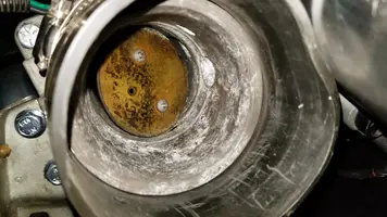
See the picture below to see the breather tube where in connects to the throttle body. It is close to the TPS and runs over the top of the IAC.
The following are diagrams courtesy of Tmoss & Stang&2birds
See the following website for some help from Tmoss (diagram designer) & Stang&2Birds (website host) for help on 88-95 wiring
http://www.veryuseful.com/mustang/tech/engine/ Everyone should bookmark this site.
Ignition switch wiring
http://www.veryuseful.com/mustang/tech/engine/images/IgnitionSwitchWiring.gif
Fuel, alternator, A/C and ignition wiring
http://www.veryuseful.com/mustang/tech/engine/images/fuel-alt-links-ign-ac.gif
Complete computer, actuator & sensor wiring diagram for 88-91 Mass Air Mustangs
http://www.veryuseful.com/mustang/tech/engine/images/88-91_5.0_EEC_Wiring_Diagram.gif
Vacuum diagram 89-93 Mustangs
http://www.veryuseful.com/mustang/tech/engine/images/mustangFoxFordVacuumDiagram.jpg
HVAC vacuum diagram
http://www.veryuseful.com/mustang/tech/engine/images/Mustang_AC_heat_vacuum_controls.gif
TFI module differences & pinout
http://www.veryuseful.com/mustang/tech/engine/images/TFI_5.0_comparison.gif
Fuse box layout
http://www.veryuseful.com/mustang/tech/engine/images/MustangFuseBox.gif