67 Super Snake Project

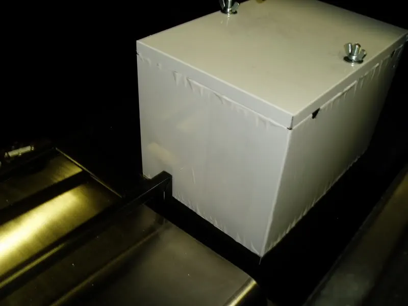
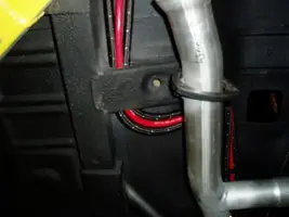
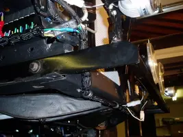
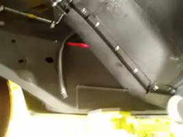
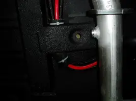
I installed the battery box and mounted it to the frame to comply with NHRA rules. I also cut through the bottom of the battery box, insulated the holes and run the cables out the bottom of the box so you cannot see any wires.
The protective covering has been left in place for now.

P9240001.webp
 

Attachments

  • P9240001.webp
    P9240001.webp
    12.6 KB · Views: 174
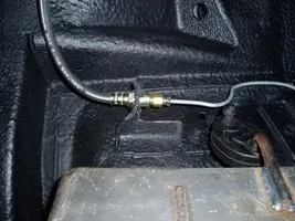
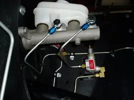
I completed the front and rear brake line and master cylinder. I went to our local O'Reilly Auto Parts and used their free double flaring tool. I needed three reducers from the Baer Brakes to the Ford lines (2 front, 1 rear).

This is the rear:
P9270001.webp


P9270002.webp


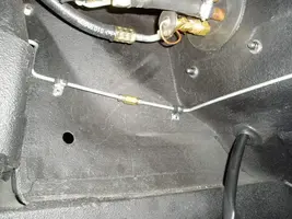
I also needed two straight connectors one for the rear and one for passenger side.

Passenger side:

P9270003.webp


I spent a lot of time bending the factory lines to make a neat installation. The 3/16" tube clamps and an #8 x 1/2" self tapping screw made it easier.

P9270004.webp


The tee and the rear adjustable proportioning valve came from UP. Things are starting to get tight for tools.

P9270005.webp


System completed!

P9270006.webp
 

Attachments

  • P9270001.webp
    P9270001.webp
    67.5 KB · Views: 190
  • P9270002.webp
    P9270002.webp
    60.1 KB · Views: 192
  • P9270003.webp
    P9270003.webp
    69.8 KB · Views: 188
  • P9270004.webp
    P9270004.webp
    63.5 KB · Views: 202
  • P9270005.webp
    P9270005.webp
    57.5 KB · Views: 181
  • P9270006.webp
    P9270006.webp
    34.6 KB · Views: 204
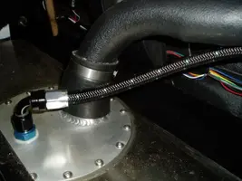
I used Russell Black AN 8 supply line and Russell Black AN 6 return line. Two 45's coming out of the tank:

P9270009.webp


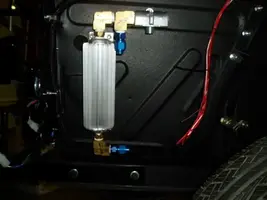
You can barely see the Aeromotive 10 micron fuel filter that I added with 2 90's:

P9270011.webp


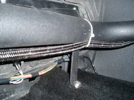
Then I run all the lines and battery cable to the front:

P9270012.webp


I used a lot of clamps to keep things straight and neat.

P9270015.webp


Routed them through the transmission mounting area. They will get a rubber insulator and a heat shield.

P9270017.webp


Ended up at the A/C area for the fuel lines. The battery cable of course went through the passenger shock tower hole to the starter relay.
 

Attachments

  • P9270009.webp
    P9270009.webp
    53.6 KB · Views: 199
  • P9270011.webp
    P9270011.webp
    24.2 KB · Views: 172
  • P9270017.webp
    P9270017.webp
    22.5 KB · Views: 177
  • P9270015.webp
    P9270015.webp
    51.7 KB · Views: 169
  • P9270012.webp
    P9270012.webp
    45.1 KB · Views: 193
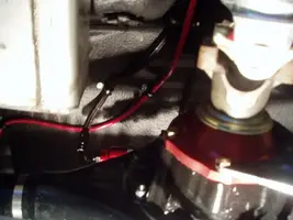
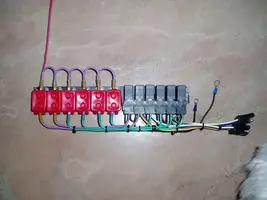
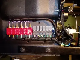
designed a relay panel to be hidden under the old battery box. 6 relays: 2 @ 50 amp - Fans, Optional (Stereo Amp), and 4 @ 30 amp - Fuel Pump, High Beams (PIAA driving lights), Low beams (stock bulbs), Fog Lamps (PIAA).

Just a note on wiring, I am using the parking/running lights to power the low beams. That way they are on all the time when the switch is pulled. The original mustang wiring turns off the low beams when the highs are on. I will use the low beam circuit to power the fog lamp circuit, and interrupt it with a switch (probably out of the dimmer switch). You usually never use the fog lamps with the high beams on.

PA010001.webp
 

Attachments

  • PA010001.webp
    PA010001.webp
    37.2 KB · Views: 207
Well I got a surprise. The parking lights do NOT stay on when switch is pulled out to the second position. So... I now have low beams ALL the time the car is started. I don't mind. But all the lights up front and in back work. Those sequential rear turn signals are trick!!


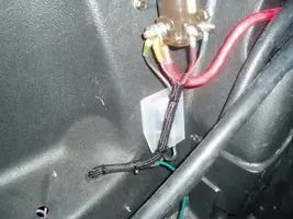
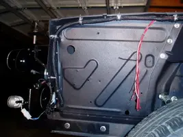
I finished the front wiring. That box below the solenoid is a 50 amp fuse for the mustang main harness. I put wire loom from the starter solenoid...

PA020010.webp


down through the passenger fender area where the relay panel is (the relay panel will get a splash shield) ...

PA020002-1.webp


down under the radiator area (I even wired it for the electric fan underneath in the middle)...

PA020003.webp


up to the driver side front (BTW, THAT fan is coming off for good, don't need it anymore)...

PA020005.webp


and under the driver side fender. That set of wires hanging down will get wire loom and then routed inside at that point. Some get hooked up to the coil that mounts on the inside of the shock tower, and the others go to the engine.

PA020006.webp
 

Attachments

  • PA020010.webp
    PA020010.webp
    65.3 KB · Views: 177
  • PA020003.webp
    PA020003.webp
    53.6 KB · Views: 187
  • PA020002-1.webp
    PA020002-1.webp
    56.4 KB · Views: 199
  • PA020005.webp
    PA020005.webp
    43.3 KB · Views: 191
  • PA020006.webp
    PA020006.webp
    52.2 KB · Views: 178
Finishing up the wiring (except for the gauges and center console), I checked all the relays and circuits. Horn works, high beams, low beams, fog lights, A/C works (blower 3 speeds and electrical to the switch on the pressure side of the cooler for the compressor clutch), back up lights (with the trans circuit bypassed), starter solenoid (with the neutral switch bypassed), all blinker, interior lights, dome, trunk light (it is always hot, I need a switch and light), fuel pump, and optional relay to stereo amp!

I started work on the gauge cluster. I installed the windshield wiper switch (no new replacement, had to use the old one)

PA040004.webp


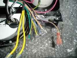
and I will post a schematic of the new Shelby gauge cluster wiring that has to be cut off and adapted to the new Painless harness tomorrow (circuit, Shelby color, painless color). Here is a start

PA040001.webp


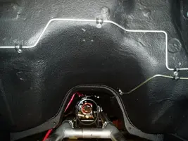
And I installed the oil cooler.
PA040007.webp
 

Attachments

  • PA040004.webp
    PA040004.webp
    22.9 KB · Views: 187
  • PA040001.webp
    PA040001.webp
    56.3 KB · Views: 170
  • PA040007.webp
    PA040007.webp
    18.3 KB · Views: 227
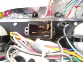
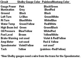
Here is the wiring schematic for using the Shelby gauges from Unique Performance and splicing it to an original or Painless wiring harness. Painless uses the same colors as the original Mustang harness.

ShelbyGaugeWiringSchematic.webp


PA070008.webp
 

Attachments

  • PA070008.webp
    PA070008.webp
    23.2 KB · Views: 188
  • ShelbyGaugeWiringSchematic.webp
    ShelbyGaugeWiringSchematic.webp
    36.6 KB · Views: 161
I installed the gas cap, fuel filler tube, 1/2' (AN-8 ) breather line, and wired the fuel pump, sending unit and the optional relay wire to the amp (not installed yet).

PA070017.webp


PA070016.webp


PA070015.webp
 

Attachments

  • PA070015.webp
    PA070015.webp
    29.6 KB · Views: 206
  • PA070016.webp
    PA070016.webp
    61.6 KB · Views: 171
  • PA070017.webp
    PA070017.webp
    58.7 KB · Views: 191
I finished all the auxiliary wiring that I could. Like wiring the trans tunnel, but from the inside so that there are no wires in the engine compartment.
The center console will cover up any deformities in the carpet, and I cut the hole way forward.

PA070012.webp
 

Attachments

  • PA070012.webp
    PA070012.webp
    39.5 KB · Views: 193
All this work allowed me to start the dash. Everything needs to be installed in this order.
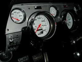
I installed the dash pad from dashesdirect.com and it is very high quality . Fit is excellent, I only had to cut two little pieces off the upper ends (by the windshield) with a pair of scissors to make it fit correctly. This piece makes the inside look better than original!

PA070007.webp


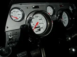
And the Shelby cluster. Everything works! I checked every circuit. And I mean every circuit!
PA070008.webp


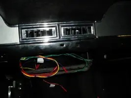
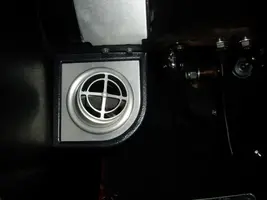
Then the A/C controls. After that the kick panels so I could install the A/C vents, run all the air tubes (what a PITA ), and cleaned up the wiring a little:

PA070010.webp


PA070006.webp
 

Attachments

  • PA070007.webp
    PA070007.webp
    45.2 KB · Views: 188
  • PA070008.webp
    PA070008.webp
    23.2 KB · Views: 191
  • PA070010.webp
    PA070010.webp
    16.4 KB · Views: 183
  • PA070006.webp
    PA070006.webp
    12.9 KB · Views: 171
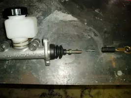
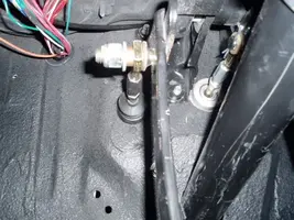
I installed the Hydraulic Clutch Master. But I had to make some modifications to the input shaft and the stock mustang adjustable brake push rod. The stock Mustang push rod adjuster is a bigger diameter/thread than the input shaft coming out of the master cylinder. And the input shaft is too long.


So, in the picture you can see how much I had to cut out of the Clutch master input shaft. How did I know how much to cut off? Fit, measure and mark. And I had to weld on a nut to the end of stock mustang push rod. And putting on that fluid reservoir was a PITA. The O'ring did not want to stay in the groove. I had to heat the plastic resevoir up with a heat gun, and work it many times to get it on without the O'ring slipping out of place. Just one more thing that takes time and patients.

PA080002.webp


PA080004.webp
 

Attachments

  • PA080002.webp
    PA080002.webp
    32.8 KB · Views: 199
  • PA080004.webp
    PA080004.webp
    58.4 KB · Views: 153
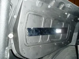
I started fitting the rear seat. If you tubbed the rear end, you must cut the rear seat. The best way to preserve the hinge mounts and end of the first fold is to cut it in the middle. Yeah, that's right. Two cuts. And then weld it together. My fenders measured only 39" clearance and the panel was 41". It now fits pretty good. I am on cloud after today. Everything is coming together!

PA080005.webp


And I had to remove the floor mounting brackets and re-weld them in by 1" each side.

Edit: I wish that I would have cut the panel off to one side or the other so the mounting holes in the new chrome pieces would line up. But I can alway just drill new mounting holes in the old metal for the one side of the chrome.
 

Attachments

  • PA080005.webp
    PA080005.webp
    34.7 KB · Views: 194
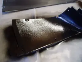
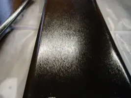
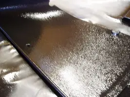
I found this paint at Home Depot. It is Rustoleum Hammered Finish. I am very pleased with because it gives you a finish very close to original.

View attachment 425910

I started with the sanded overhead rear piece with absolutely no finish

View attachment 425912

and got this finish

PA110011.webp


PA110016.webp


Rear Inside corner

PA110009.webp
 

Attachments

  • PA110009.webp
    PA110009.webp
    25.5 KB · Views: 183
  • PA110016.webp
    PA110016.webp
    35.1 KB · Views: 186
  • PA110011.webp
    PA110011.webp
    52.9 KB · Views: 184
I mounted the new transmission crossover. Bolted it in and had to drill out to 1/2" for the new grade 8 bolts to help handle the horsepower. A piece will be welded in place that mounts up to the trans when I get the engine/transmission in place.

PA110002.webp
 

Attachments

  • PA110002.webp
    PA110002.webp
    14.5 KB · Views: 167
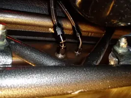
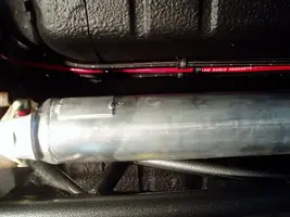
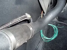
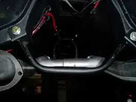
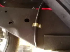
I insulated the fuel lines and battery cable with a radiator hose cut in half and stuck it through the cross brace to eliminate any chafing.

PA110001.webp


I then installed the heat shields that I fabricated to help reduce the heat from the headers. This should help keep the fuel cooler!

PA110005.webp


PA110006.webp


I even bolted down the A/C drain line so it would not touch and melt to the header.

PA110008.webp
 

Attachments

  • PA110008.webp
    PA110008.webp
    12 KB · Views: 183
  • PA110006.webp
    PA110006.webp
    16.9 KB · Views: 166
  • PA110005.webp
    PA110005.webp
    12.9 KB · Views: 193
  • PA110001.webp
    PA110001.webp
    21.5 KB · Views: 196