
You are using an out of date browser. It may not display this or other websites correctly.
You should upgrade or use an alternative browser.
You should upgrade or use an alternative browser.
67 Super Snake Project
- Thread starter 67FBack
- Start date
-
Sponsors (?)
Sicarius428
Active Member
- Jan 6, 2004
- 2,085
- 5
- 49
Yes! Progress? I think you should get a viper spec t56. Then are rated for 700 ft lbs which is closer to your area than a TKO600 which is rated for 600. I am also being selfish because I wanna back my FE with a T56 and using you as a ginnie pig. Hope you don't mind.
Kevin
Kevin
mdjay
Premium Sponsor
Sicarius428 said:Yes! Progress? I think you should get a viper spec t56. Then are rated for 700 ft lbs which is closer to your area than a TKO600 which is rated for 600. I am also being selfish because I wanna back my FE with a T56 and using you as a ginnie pig. Hope you don't mind.
Kevin
Actually UP has bench tested the tko600 to 1200 hp!
70vert
New Member
Wheel to UCA clearance? You using 17s?
Richard,
Amazing project. Looks like you and I have similar taste in some of the parts, though I'm on a bit more of a budget - even still, I get accused of buying spendy parts.
I have a problem with my (earlier) set of UP coilovers. Where the UCA comes out, it hits my 17x8, 4.75bs Coy's C-67 rims: (Eleanor style)
http://homepage.mac.com/jbauder/PhotoAlbum77.html
It only happens on hard braking, but still. I have a 5/16" spacer on there and the right side (non-driver) scrapes the UCA a little on hard braking. I have filed down the UCA and the rim has a few scrapes on it, but it still happens.
Question is, when you look at my photo there, does it look like your UCA, or is yours more round and less teardrop-shaped? I have heard that they redesigned that and I have an email in to them with no reply. What's your wheel size there, 17x8"? 4.5bs?
Thanks in advance, should help me figure out a few things.
Joe
Sicarius428
Active Member
- Jan 6, 2004
- 2,085
- 5
- 49
jcode68
Active Member
70vert said:Richard,
Amazing project. Looks like you and I have similar taste in some of the parts, though I'm on a bit more of a budget - even still, I get accused of buying spendy parts.
I have a problem with my (earlier) set of UP coilovers. Where the UCA comes out, it hits my 17x8, 4.75bs Coy's C-67 rims: (Eleanor style)
http://homepage.mac.com/jbauder/PhotoAlbum77.html
It only happens on hard braking, but still. I have a 5/16" spacer on there and the right side (non-driver) scrapes the UCA a little on hard braking. I have filed down the UCA and the rim has a few scrapes on it, but it still happens.
Question is, when you look at my photo there, does it look like your UCA, or is yours more round and less teardrop-shaped? I have heard that they redesigned that and I have an email in to them with no reply. What's your wheel size there, 17x8"? 4.5bs?
Thanks in advance, should help me figure out a few things.
Joe
Not sure this helps, but your pics show a drum brake setup, which may be affecting the wheel position off the spindle. Your sig indicates disc brake setup, have you just not put them on yet?
Progress? Well here is 3 months worth of progress...
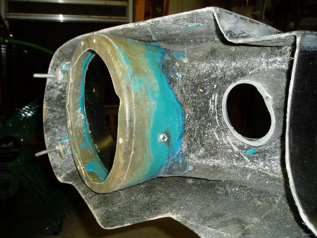
I installed the headlight buckets in the upper nose, and installed the front fender brace.
I had to remove this small bracket

Put the headlight in the bucket


 G]
G]
And 5885 epoxy glued it in place
I installed the headlight buckets in the upper nose, and installed the front fender brace.
I had to remove this small bracket
Put the headlight in the bucket
And 5885 epoxy glued it in place
Attachments


I installed the Flaming River steering column. This is the new lower plate that hold the column at the firewall. The tabs get bent in, and are used to hold the column.

Mounted the knuckles to the R&P and the column.

I marked and drilled the intermediate shaft for setscrew indent. The devil is in the details.


Then I installed one of the seats. The seat bracket is installed incorrectly here. I installed it with the seat toward the front, and all the way up. It needs just the opposite. In fact, if I were to know how it sets now at the beginning, I might not install the seat pans. I would probably do something else, and I might still change things. Also make sure you move the seat latch rod on the left adjuster, from the back to the front hole. And when attaching it to the right side, bend that sucker so it does not come out! I found out the hard way.
Seat bracket.

Installed wrong, Need to be at the top (arrow):

Seat adjuster rod (circle) moved to the front hole. Bend that sucker to where it cannot come out (arrrow):

Seat bracket installed correctly! (towards the back):

Mounted the knuckles to the R&P and the column.
I marked and drilled the intermediate shaft for setscrew indent. The devil is in the details.
Then I installed one of the seats. The seat bracket is installed incorrectly here. I installed it with the seat toward the front, and all the way up. It needs just the opposite. In fact, if I were to know how it sets now at the beginning, I might not install the seat pans. I would probably do something else, and I might still change things. Also make sure you move the seat latch rod on the left adjuster, from the back to the front hole. And when attaching it to the right side, bend that sucker so it does not come out! I found out the hard way.
Seat bracket.
Installed wrong, Need to be at the top (arrow):
Seat adjuster rod (circle) moved to the front hole. Bend that sucker to where it cannot come out (arrrow):
Seat bracket installed correctly! (towards the back):
Attachments


After I got everything installed, I set in it and , lock to lock is only 2 turns!!!!
That is good, however the turning radius sure looks like it could be tighter:


Get Er Done View attachment 426094 View attachment 426096 View attachment 426098
That is good, however the turning radius sure looks like it could be tighter:
Get Er Done View attachment 426094 View attachment 426096 View attachment 426098
Attachments


Installed the upper rear scoops.
Ground down to metal for the bonding agent.

Taped it off and painted the fins and inside scoops gloss black.


Removed the tape.

Ground off the paint around the edges and trimmed it a little.

Squeezed out the bonding agent and spread it out. I put the bonding agent on the car and spread it, also.

Ground down to metal for the bonding agent.
Taped it off and painted the fins and inside scoops gloss black.
Removed the tape.
Ground off the paint around the edges and trimmed it a little.
Squeezed out the bonding agent and spread it out. I put the bonding agent on the car and spread it, also.
Attachments


I plunged head first into what I thought would be something difficult. Turns out the decision was the difficult part.
I laid out the fuel filler pipes. While helpful, there is no clear point to install it.

So I tried to find a place that the filler tube would fit without cutting the inside:

That put the gas cap only 4 1/2" from the trunk line. Way too far back for me.

So then I looked through all of the picture that I had of the UP cars. This is what I found. And look at the red circle. They cut the inside metal.

So, I put it where I wanted it. Found a good spot on the inside. Looked at it from the outside. It measured 8 1/2" from the trunk line.

Now for the cutting tools.

It cuts a clean circle. Thank you Lou and Jarred from Muscle Car TV.

Welded a little ring around the outside.

Now, how do I cut the hole in the fender? Use the radius arm. Here goes nothing.

You will have to cut an inside piece. Note how the pipe fits perfectly.

Welded everything in. Now to cut out the center hole using the handy radius arm one more time.

And the finished product. No bondo needed here!

I laid out the fuel filler pipes. While helpful, there is no clear point to install it.
So I tried to find a place that the filler tube would fit without cutting the inside:
That put the gas cap only 4 1/2" from the trunk line. Way too far back for me.
So then I looked through all of the picture that I had of the UP cars. This is what I found. And look at the red circle. They cut the inside metal.
So, I put it where I wanted it. Found a good spot on the inside. Looked at it from the outside. It measured 8 1/2" from the trunk line.
Now for the cutting tools.
It cuts a clean circle. Thank you Lou and Jarred from Muscle Car TV.
Welded a little ring around the outside.
Now, how do I cut the hole in the fender? Use the radius arm. Here goes nothing.
You will have to cut an inside piece. Note how the pipe fits perfectly.
Welded everything in. Now to cut out the center hole using the handy radius arm one more time.
And the finished product. No bondo needed here!
Attachments
-
 P8220008.jpg100.8 KB · Views: 130
 -
 P8220007.jpg83.7 KB · Views: 153
 -
 P8220011.jpg69.1 KB · Views: 134
 -
 Picture092-1.jpg53.3 KB · Views: 112
 -
 P8220006.jpg70 KB · Views: 115
 -
 P8220002.jpg103.2 KB · Views: 132
 -
 P8220003.jpg87.3 KB · Views: 133
 -
 P8220008-011.jpg91.8 KB · Views: 136
 -
 P8220008-015.jpg101.6 KB · Views: 109
 -
 P8220008-01.jpg64 KB · Views: 134
 -
 P8220008-014.jpg106.1 KB · Views: 124
 -
 P8220013.jpg82.4 KB · Views: 122
I dropped the front and rear running gear, and prepared the entire car for undercoating.
I shot the underside with 2 coats of Lizard Skin Sound Control and 2 coats of Lizard Skin Ceramic Heat Insulation. This stuff is pretty thick and should work well. However, I did not like the ending color. It turns out very flat.
You will definitely need a light to see under the car when you are shooting.

Pictures are washed out. It is a little black, but very flat in color.

This is more how it really looks.

I went ahead and shot one more coat of a product called Total Control. It is a glossier black, and has an orange peel finish. I went ahead and shot the engine compartment with this and I like how it turned out.
I replaced the U&LCA's, spindles, brakes, tires, R&P, and coilover rear end. All in about 3 hours.
I shot the underside with 2 coats of Lizard Skin Sound Control and 2 coats of Lizard Skin Ceramic Heat Insulation. This stuff is pretty thick and should work well. However, I did not like the ending color. It turns out very flat.
You will definitely need a light to see under the car when you are shooting.
Pictures are washed out. It is a little black, but very flat in color.
This is more how it really looks.
I went ahead and shot one more coat of a product called Total Control. It is a glossier black, and has an orange peel finish. I went ahead and shot the engine compartment with this and I like how it turned out.
I replaced the U&LCA's, spindles, brakes, tires, R&P, and coilover rear end. All in about 3 hours.
Attachments


Putting the car back together after the undercoating. I have got many thing accomplished.
Installed the exhaust system. Putting the exhaust through the rear torque boxes is a challenge. It took me 1 1/2 days to finish.

Muffler is only tacked on inlet side at this point.

With a little ingenuity you can size down the hole in the rocker to only this small access hole for the exhaust tip clamp.

Welded in the drive shaft safety loop.

Installed the exhaust system. Putting the exhaust through the rear torque boxes is a challenge. It took me 1 1/2 days to finish.
Muffler is only tacked on inlet side at this point.
With a little ingenuity you can size down the hole in the rocker to only this small access hole for the exhaust tip clamp.
Welded in the drive shaft safety loop.
Attachments


Installing the rear lights need a lot of attention and time. I mounted the studs to the rings with loctite red. Made sure everything fits right. Lenses go in from the inside. I had to cut some more of the tail panel. But it looks good. Cant see it from this picture though.
I installed the trunk carpet. Good scissors and the right carpet make for a fine fit. I got the carpet from UP. It is thin enough to be mold-able.
Then I installed the fuel cell and the nitrous bottle bracket.

I installed the trunk carpet. Good scissors and the right carpet make for a fine fit. I got the carpet from UP. It is thin enough to be mold-able.
Then I installed the fuel cell and the nitrous bottle bracket.
Attachments


And I have completed 90% of the Painless Wiring 14 circuit system for the Mustang. I am pleased with the kit. Very easy. I just wished it had more than 1 extra relay. I will use it for the electric windows. I will have to add 6 extra circuits for the high amp items like High Beams, Low Beams, Driving Lights, A/C Cooling Fan and Clutch, the Electric Radiator fan and the fuel pump.
Here is the UP taillight sequential wiring harness. I liked how it eliminated all the cutting and crimping. It connects to the PIAA back up lights (connectors already there). You only have four wires to hook up and a ground. You will have to put on your own connector to the rear harness. I just cut off a four wire connector from the old harness and spliced it on to the new one.


This is the dash wiring. Believe it or not it is almost finished. Only the radio wiring, one glove box wire needing to be capped, connecting the driving lights to a switch, and connecting one "Old Air" orange wire to a switched hot. What worked: the Painless kit fit very well. What didn't work: only one extra interior circuit, GM column wires had to be cut and spliced with the provided connector.
And if you are really counting, I had yet to install the wiring for the console. It will have the power window switches, couple of gauges (probably boost and oil temp), and of course the nitrous switch.

I decided to hide the wiring as much as possible. I routed the wires out to the drivers fender,

Up under the wheel well, (the bolts are #8 x 1/2" self tapping screws and will be ground off, then hidden by the fenders)

and out the front under the lower nose.


This is not a finished project at this point. I am going wire tie it up better and use wire loom to protect the wires. This is where I am building my relays and fuse block for the major current draw items. (High Beams, Low Beams, Driving Lights, Fuel Pump, A/C Radiator Fan-A/C Clutch, and Engine Electric Radiator Fans. Note the detail. Every place there is a chance for scuffing, I have installed a rubber insulator.

Here is the UP taillight sequential wiring harness. I liked how it eliminated all the cutting and crimping. It connects to the PIAA back up lights (connectors already there). You only have four wires to hook up and a ground. You will have to put on your own connector to the rear harness. I just cut off a four wire connector from the old harness and spliced it on to the new one.
This is the dash wiring. Believe it or not it is almost finished. Only the radio wiring, one glove box wire needing to be capped, connecting the driving lights to a switch, and connecting one "Old Air" orange wire to a switched hot. What worked: the Painless kit fit very well. What didn't work: only one extra interior circuit, GM column wires had to be cut and spliced with the provided connector.
And if you are really counting, I had yet to install the wiring for the console. It will have the power window switches, couple of gauges (probably boost and oil temp), and of course the nitrous switch.
I decided to hide the wiring as much as possible. I routed the wires out to the drivers fender,
Up under the wheel well, (the bolts are #8 x 1/2" self tapping screws and will be ground off, then hidden by the fenders)
and out the front under the lower nose.
This is not a finished project at this point. I am going wire tie it up better and use wire loom to protect the wires. This is where I am building my relays and fuse block for the major current draw items. (High Beams, Low Beams, Driving Lights, Fuel Pump, A/C Radiator Fan-A/C Clutch, and Engine Electric Radiator Fans. Note the detail. Every place there is a chance for scuffing, I have installed a rubber insulator.
Attachments


Similar threads
- Replies
- 4
- Views
- 521
- Replies
- 61
- Views
- 3K
- Replies
- 0
- Views
- 178
- Replies
- 2
- Views
- 1K