88 LX Coupe STILL$$ running pig rich, running out of ideas.

mavmavv

New Member
Nov 21, 2007
185
0
0
First of all, im pulling codes:
21-Coolant Temp Sensor
94-AIR injection
18-Timing

The thing is, I have a brant new coolant temp sensor, my AIR injection solenoid might be out, but it shouldnt effect the richness or drivability at all. Code 18 sometimes shows up, not always.

Ive replaced almost all the sensors, ECT, BAP, PIP, TPI, cleanred the MAF. Replaced the coil. Adjusted the TPS, etc.
Checked and rechecked the vacuum, getting 20+" at idle. My fuel pressure is a steady 30PSI at idle and higher when the engine revs.

The car stumbles all over its self under 1500RPM and its pig rich throwing out smoke out of the pipes. Ive checked the vaccum regulaor for the fuel, no fuel coming out, is this a surefire sign its ok? Could it be stuck open or something?
 
The code 21 can also be from bad wiring. If the computer thinks the engine is cold, it will add fuel. This can cause a rich condition.
Measure the ECT output voltage at the computer using the instructions below to make sure the wiring is good.
Be sure to warm the engine up before doing any testing.

Code 21 – ECT sensor out of range. Broken or damaged wiring, bad ECT sensor.
Note that that if the outside air temp is below 50 degrees F that the test for the
ECT can be in error.


The ECT sensor has absolutely nothing to do with the temperature gauge. They are
different animals. The ECT sensor is normally located it the RH front of the engine in
the water feed tubes for the heater.

The ACT & ECT have the same thermistor, so the table values are the same

ACT & ECT test data:

Use Pin 46 on the computer for ground for both ECT & ACT to get most accurate
readings.

Pin 7 on the computer - ECT signal in. at 176 degrees F it should be .80 volts

Pin 25 on the computer - ACT signal in. at 50 degrees F it should be 3.5 volts. It is
a good number if the ACT is mounted in the inlet airbox. If it is mounted in the lower
intake manifold, the voltage readings will be lower because of the heat transfer.

Voltages may be measured across the ECT/ACT by probing the connector from
the rear. A pair of safety pins may be helpful in doing this. Use care in doing it
so that you don't damage the wiring or connector.

Here's the table :

50 degrees F = 3.52 v
68 degrees F = 3.02 v
86 degrees F = 2.62 v
104 degrees F = 2.16 v
122 degrees F = 1.72 v
140 degrees F = 1.35 v
158 degrees F = 1.04 v
176 degrees F = .80 v
194 degrees F = .61
212 degrees F = .47 v
230 degrees F = .36 v
248 degrees F = .28 v

Ohms measures at the computer with the computer disconnected, or at the sensor with the sensor disconnected.

50 degrees F = 58.75 K ohms
68 degrees F = 37.30 K ohms
86 degrees F = 27.27 K ohms
104 degrees F = 16.15 K ohms
122 degrees F = 10.97 K ohms
140 degrees F = 7.60 K ohms
158 degrees F = 5.37 K ohms
176 degrees F = 3.84 K ohms
194 degrees F = 2.80 K ohms
212 degrees F = 2.07 K ohms
230 degrees F = 1.55 K ohms
248 degrees F = 1.18 k ohms

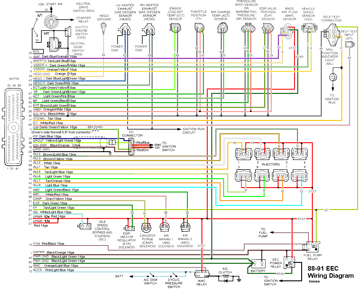
Diagram courtesy of Tmoss & Stang&2birds

88-91_5.0_EEC_Wiring_Diagram.gif


See the following website for some help from Tmoss (diagram designer) & Stang&2Birds
(website host) for help on 88-95 wiring http://www.veryuseful.com/mustang/tech/engine/

Ignition switch wiring
http://www.veryuseful.com/mustang/tech/engine/images/IgnitionSwitchWiring.gif

Fuel, alternator, A/C and ignition wiring
http://www.veryuseful.com/mustang/tech/engine/images/fuel-alt-links-ign-ac.gif

Complete computer, actuator & sensor wiring diagram for 88-91 Mass Air Mustangs
http://www.veryuseful.com/mustang/tech/engine/images/88-91_5.0_EEC_Wiring_Diagram.gif

Vacuum diagram 89-93 Mustangs
http://www.veryuseful.com/mustang/tech/engine/images/mustangFoxFordVacuumDiagram.jpg
 
I had a similar problem with mine...

1. Could be a stuck fuel pressure regulator, dumping fuel...but probably not.

2. More likely a stuck fuel injector...When you turn the ignition foreward so the fuel pump powers up, if your standing by the engine bay(while someone else turns the ignition foreward obviously) can you hear a hissing/squirting/splooshing sound?

That was my case, i could hear a hissing sound, it was the injector stuck open dumping fuel in the intake.

You can test this, its a little tough.

While the engines running, unplug each injector one by one. in other words unplug one, listen, and plug it back in, then do the next one. If you get to unplugging one and the car still runs better and not as rich, its probably that injector that needs replacing.

I hope this helps you:nice: , it helped me get my engine in shape after fretting over it for a LONG time.
 
Thanks guys for the suggestions and help. Ill definitely probe the sensors.

I DO here a slushing splooshing sound after I shut off the motor and only 1 tailpipe seems to be rich at idle. That very well could be evidence of a bad injector. I have pretty much replaced everything else.

I have a question about checking the injectors though. How am I supposed to check them with the motor on? Wouldnt this send fuel flying out? And how am I supposed to take them out with the upper intake on? Could you please explain further? The motor has 130xxx miles on it, its probably time for a new set of injectors anyways.

By the time im done with this thing, its gonna have all brand new externals. :D

I will also check the fuel return line. Thanks guys.
 
WOOOOOO!!! I ran an cylinder balance test and came up with cylinders 2 and 5, unplugged 5 and BAM! ran better than it ever has on 8 cylinders. Im gonna order some injectors tomorrow and replace atleast those 2.
 
Some more thoughts on ground you may have already covered...

Fuel pressure OK, the injectors are not firing, OR one or more injectors stuck
open

Do a cylinder balance test: Warm the car's engine up to normal operating
temperature. With the Engine Off, Key OFF, use a jumper wire or paper clip to
put the computer into test mode. Start the engine and let it go through the
normal diagnostic tests, then quickly press the throttle to the floor. The
engine RPM should exceed 2500 RPM's for a brief second. The engine will shut
off power to each injector, one at a time. When it has sequenced through all
8 injectors, it will flash 99 or the number of the failing cylinder such as 22 for
cylinder #2. Quickly pressing the throttle again up to 2500 RPM’s will cause
the test to re-run with smaller qualifying figures. Do it a third time, and if the
same cylinder shows up, the cylinder is weak and isn’t putting out power like
it should. See the Chilton’s Shop manual for the complete test procedure

The red wire on each injector is powered up whenever the ignition switch is
in the Run position. The computer provides a ground to complete the circuit
and fire the injector. The injector must have a ground to squirt fuel on
command. A short to ground in the injector return wiring can cause one or
more injectors to be continually open or triggered
A.) A Noid light available from Autozone, is one way to test
the injector wiring. If the light stays on constantly, either the wiring has a
short to ground or the computer has failed

B.) I like to use an old injector with compressed air applied to the
injector where the fuel rail would normally connect. I hook the whole thing
up, apply compressed air to the injector and stick it in a paper cup of soapy
water. When the engine cranks with the ignition switch on, if the injector
fires, it makes bubbles An injector stuck open will release a continual stream
of bubbles. Cheap if you have the stuff laying around, and works good too.
The same trick works great to find leaking injectors too.​
The wiring for the injectors may have some bare spots in it causing the
injector to computer control wire to ground out. This would cause the
injector to remain on anytime the key was in the Run position. Remove the
injector wiring connectors from the injector. Note that each injector has one
red wire for power and a non red wire (wire some color other than red) for
computer controlled ground. With the key off, disconnect the computer
connector from the computer. Use an Ohmmeter between the non red wire
and ground. You should see more than 100000 (100K) ohms resistance.


See the following website for some help from Tmoss (diagram designer) &
Stang&2Birds (website host) for help wiring http://www.veryuseful.com/mustang/tech/engine/

Diagram courtesy of Tmoss & Stang&2birds

88-91_5.0_EEC_Wiring_Diagram.gif


Using the above diagram, check the resistance between the injector and the
computer. Clean and check the 10 pin connectors since they are a potential
trouble source. Any resistance greater than 1.5 ohm between the injector to
computer wire and the matching pin on the computer connector is a problem.

harness02.gif


See http://fordfuelinjection.com/?p=6 for more help

Here's the link to dump the computer codes with only a jumper wire or paper
clip and the check engine light, or test light or voltmeter. You’ll need it to do
the cylinder balance test

See http://www.troublecodes.net/Ford/

index.php


index.php


IF your car is an 86-88 stang, you'll have to use the test lamp or voltmeter method. There is no functional check engine light on the 86-88's except possibly the Cali Mass Air cars.

attachment.php


89 through 95 cars have a working Check Engine light. Watch it instead of using a test lamp.

attachment.php
 
Yeah, im gonna have to still track down that wiring gremlin for the ECT sensor. Atleast I can drive it now without having my eyes water.

Next up is cleaning up the body and spraying some flat black. :D
 
So, I replaced the injector, it seemed to somewhat help, but pretty quickly became rich again. So I played with the timing a little and advanced the hell out of it to deal with the richness, it seemed to like that.

Took it out for a drive, its at least drivable now and has decent power. Its still reall rich, if I put my foot in it or come to a stop I can definitely smell HEAVY unburnt fuel. When the car idles it feels like its missing or it has a decent sized cam. Ive replaced everything but the wires in the ignition, the wires very well could be bad, I wouldnt doubt it.

But anything under 1000RPM has a pretty bad "miss" feel to it. I took the ECT and ACT sensors out and cleaned them for any grime. No go.

When I did a couple KOEO tests the throttle was sticking high, this is the sign of a bad TPS sensor, right? Would that effect my a/f mixture that heavily? When I measured the voltage at idle it would climb to 1.2~V. Idle is supposed to be .6-1.0V, yes? Any ideas? This seems to be computer related since I tested the crap out of the fuel pressure regulator and the front half of the injectors (didnt have time to test the back 4 :(

Ugh. Better get to studying, got finals this week.
 
Ok, so ive checked everything I can think of.

The ECT sensor is actually INCREASING in voltage as the temp rises. Does this mean I have a bad ground somewhere? I know its supposed to decrease. I tried both my old sensor and my new one, both were increasing in voltage as the car temp rose.

Im running out of ideas of where to look. I checked the grounds to the firewall/engine, both were good. Any other places to check?
 
Look at the diagram I posted showing the engine computer wiring. The ECT uses a separate
signal ground that is not connected to the engine block or car body until it passes through the computer.

The computer pin 46 signal ground is a critical component: it provides ground for the
TPS, ECT, EGR position sensor and ACT. Signal ground is used in many circuits that have
analog inputs to isolate the electrical noise. It is always separate from power ground,
although both may have a common connection origination point. Signal ground usually
has some conditioning that reduces the electrical noise to prevent false readings
The black/white wire (pin 46) is signal ground for the computer. It provides a dedicated
ground for the EGR, Baro, ACT, ECT, & TPS sensors as well as the ground to put the
computer into self test mode. If this ground is bad, none of the sensors mentioned
will work properly. That will severely affect the car's performance. You will have hard starting,
low power and drivability problems. What sometimes happens is that the test connector black/white
wire gets jumpered to power which either burns up the wiring or burns the trace off the
pc board inside the computer. That trace connects pins 46 to pins 40 & 60.
Only an experienced electronics technician can open the computer up & repair the trace if it burns
up and creates an open circuit.

If the ground for the TPS goes bad, the TPS output voltage increases and the idle speed goes up.

attachment.php


Troubleshooting signal ground problems:

Note that all resistance tests must be done with power off. Measuring resistance
with a circuit powered on will give false readings and possibly damage the meter.


1.) With the power off, measure the resistance between the computer test ground
(black/white wire) on the self test connector and battery ground. You should see less than 2.0 ohms.

attachment.php


2.) MAP circuit: Check the resistance between the black/white wire on the MAP/BARO sensor
and then the black/white wire on the EGR and the same wire on the TPS. It should be less than 1 ohms.
Higher resistance than 1 ohms indicates a problem with the 10 pin connector or the splice
inside the main harness where the wire from the 10 pin connectors joins the rest of the black/white wire.
Next check the resistance between the black/white wire and the negative battery cable.
It should be less than 2.0 ohms.

3.) Engine mounted sensor circuit: Check the resistance between the black/white wire on the TPS
and battery ground. It should be less than 2.0 ohms. Higher resistance than 2.0 ohms
indicates a problem with the 10 pin connector or the splice inside the main harness where the
wire from the 10 pin connectors joins the rest of the black/white wire.
Repeat the process for the ACT and ECT sensors. Your results should have the same specifications.

attachment.php