My 8 trumpet Manifold Project.

Ozrunner

Member
Nov 4, 2005
44
1
6
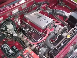
Guys I don't have a Stang but a Oz 1991 4Runner which I fitted with a HO 5.0Mustang Cobra engine way back in 1993 while it was still under a Toyota warranty, :D Its also ungone a lot of other changes since I brought it along with additional engine mods.

The following are details of the fabrication project so its past tense :D

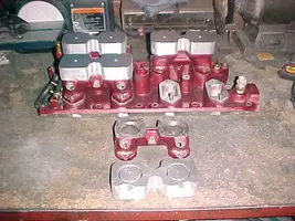
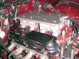
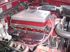
I previously made two different upper manifolds as I didn't like the stock Ford unit and mine worked better anyway, ;D. It looked like this and the middle section is actually a cover over the manifold I made.

010.jpg


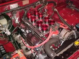
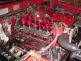
But I am now working on an entirely new upper and lower efi setup using 8 trumpets. I have a spare engine set up to build it on so when its finished its a simple matter of swapping it onto my engine. Originally the plan was to use this setup but after investigation it was evident that the front stacks and dizzy were just too close to be able to be used.

M8.jpg


The stock dizzy has a very large cap and there didn't seem to be an easy way of getting around it as this pic shows. The plate section also needs to come forward another 20mm so I had to consider alternatives. I was at one stage about to make an adapter plate for my dizzy to use a smaller cap.

M15.jpg


But I then located a stock replacement Mallory dizzy in the US that also had a small cap option and this provided the solution provided I rearranged the leads to obtain better clearance etc. But the stacks bellmouths were still too big so the obvious step was to get some stacks with a smaller bellmouth, which I did and along wth the new dizzy there appeared to be just enough space, but it would all have to be fabricated with nothing to spare.

The first step was to make the main plate section and a cover that would clear the stacks and dizzy etc. This was a real challenge being a touch fit so I have had to fabricate everything and then clamp it together exactly where I wanted it welded and so far all is going to plan.

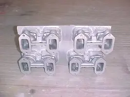
This is the main plate section with new smaller stacks.

M19.jpg


This was the box clamped up as the front area was critical and had to be welded exactly as clamped.

M17.jpg


It was starting to come together. I planned to remove the stack base plates so I could press them directly into the plate.

M20.jpg


And now the top section clamped to the welded lower.

M18.jpg


Once that was done and test fitted I then worked on finishing the top plate section and drilled all the extra holes required to mount the sealing bead section on the plate and its currently as per this pic.

M30.jpg


The next step was to mount the throttle body and I was going to mount it using a tube extension as per below but decided it would look better if mounted directly on the cover.

M26.jpg


This meant I would have to cut the fuel rails but this was not a big deal although once again clearance was an issue but I managed to overcome this and its now basically on and this is where I am at. I am fabricating a cover section for the throttle body and injectors and fitting cover mounting bolt sections.

M28.jpg


Its been a challenging project so far and I will post updates as they happen, ;D.

JD
 
UPDATE

Its now basically done except for the TB and injector covers, which I am redoing as I wasn't happy with the original outcome. During the week I will test fit the Mallory to my engine using an altered firing order pattern to ensure there will be no problems etc and mark where it will be positioned. I can then install it correctly for initial startup when I do the complete swapover.

I've also made 20mm plastic rocker cover spacers so I can fit the rocker girdles. The spacers lift the rocker covers up and to some extent they hide the 8 throttle bodies but I want to run the girdles so its hard luck, ;D. But the cover lift makes the engine look a lot wider, ;D

I plan to make a start next weekend on the swapover as rather than take a guess I would rather position the new lower manifold section in place in order to be able to work out exactly where the various water lines need to be positioned. Rather than use the former Ford set where the heater water comes from the thermostat area I have tapped into the rear of the heads. I have also incorporated my previous set up where separate lines join into the heater return tube from the rear of each head and all water returns to the waterpump. I currently also use this set up to ensure that there were no hot spots or air locks in the rear of the heads etc.

I also have to make a new throttle cable support bracket as my current set up cannot be reused. I have installed an adjustable Malpassi fuel pressure regulator at the rear of the cover and its all ready to plumb in the fuel lines etc.

Once I've done all the water lines etc etc I then have to do the crap bit and prepare all the bits and paint them and then it can all be finally installed ;D

This pic shows the cover bolt downs now welded in place and they are positioned to contact the edging bead so the cover can be torqued down. I will file a gap of about 1mm off the cover bottom edging as I plan to use a strip of 6mm wide by 3mm thick sticky back rubber around the sealing edge so when the covers torqued down it will compress 2mm etc.

M35.jpg


I've now made the 30mm plastic spacers under the main plate and match ported the complete setup. I am hoping the actual head ports will be a good match to the new lower manifold as I don't intend to remove the heads at this point in time.

M40.jpg


I plan to install the trumpets last as they will be locked in with a special locktite goo.

M36.jpg


This shows the underside and you can also see the PCV valve is now located in the former throttle linkage locating pole.

M34.jpg


Hard to see but the 6 cap screw bolts are sunk into the cover. I am redoing the top section of the TB cover and the injector covers.

M32.jpg


M33.jpg
 
UPDATE

Other than painting the top cover its all done and I'm now finishing the final install.

This shows the former quad throttle linkage pole now machined for the PCV system.

M47.JPG


This is an extension welded under the manifold in the separate manifold vacuum chamber for a PCV fitting.

M48.JPG


The vacuum chamber sealed off. The main outlet is in the top cover plate between the front 4 stacks.

M49.JPG


The top plate and fuel rails are polished and the manifold painted and ready for install.


M62.JPG


M61.JPG


The injector covers have been welded on although I've since had the front corner of the right cover redone so its indented the same as the left. So I can remove the cover as a total package I located the throttle position sensor an idle speed control plugs under the rear left injector cover and made it so it swivels up to allow these plugs to be easily disconnected.


M43.JPG


A brief comparison of the old and the new.


M67.JPG


Now bolted on and I'm currently doing the final assembly. The stainless water return tube was a real bitch to form bend. That stuff is strong, :D


M69.JPG


M71.JPG


The fuel lines, wiring etc are designed and fitted in such a way that I can easily remove either as a complete setup, if required. I fitted the fuel pressure reg at the rear of the main plate and although it fits fine its location has made access to the rear a tad crowded. Later I may take the opportunity to re locate it to free up this area.

Since this pic was taken I have altered the fuel pressure lines so they crossover and connect on the opposing side so as to avoid kinks forming. You can also see the rear head water outlets I use that feed back to the water pump so as to avoid any rear hots spots. The sensor plumbed into # 4 inlet is the air temp sensor.

The brake vacuum and 4wd selection vacuum line pick up from the separate vacuum chamber under the manifold. Vacuum sensing for the fuel pressure reg comes from a fitting via the main plate into the boxed plenum area.

M55.JPG


I'll have to get some simple stack covers as if I now drop anything down a stack I'm in deep trouble, :D .

JD
 
For those wondering what has been happening with this project, :D

To cut the story short I decided that the initial version above would be prone to air leaks and possible problems etc due to the many bolts, holes and gasket so after a lot of thought I decided the only answer was to completely remake it to eliminate this possibility.

This time I used alloy spacers so they could be fully welded to each housing and then welded to the top main plate as this would eliminate 32 bolts and 16 small gaskets. Also by using a thicker main plate its sides could be machined for an O ring seal to get rid of the former 12mm square bar edging and its 12 bolts.

I made 4 alloy spacers and precut them to match the bore of each injector housing but cut them just short of coming through the top. I then fitted 2 small locating pins in each so the welder guy couldn't screw up their location on the housings, :D Thankfully. I've now found a young guy who is a gun alloy welder.

M78.webp


After they were welded to the housings I then positioned the top plate on the 4 housings and using the pre drilled centre holes as a marker drilled the main plate and bolted each injector housing to the plate so they could be welded in the exact position.

M83.webp


Fully welded and the top and bottom surfaces faced.

M88.webp


Again using the centre guide holes I then cut through the main plate and the remaining bit in the injector housing spacers. Also I made access to the inner base flange bolts via a common cover machined into the main plate rather than use the former brass plugs.

The top manifold is now a complete one piece alloy unit without any bolts or gaskets, :D . The only holes are the main 8 plus 2 for the PCV and fuel pressure vacuum brass fittings. The three central access holes are blanked by a sealed cover and the main cover bolt holes are blind. The O ring groove is much better as it only takes seconds to feed a strip of O ring rope into the edging.

Initially, I wasn't too happy about doing it all again but it was a wise move as this setup will be infallible.

M87.webp


CURRENT UPDATE .

Its finished and I've been doing a lot of miles but so far I haven't completed a cruising mpg test. It boogies and although purposedly built as a low compression engine it hits the factory 6250 rev limiter way too easy, :D

I also added a 70mm US Accufab throttle body and the only issue occurs at wide open throttle (WOT) but its a good sign. My engine currently uses 19lb injectors and the air/fuel gauge is showing that as the injection is flowing a *****load more air at WOT the 19's flow limit is maxing out. It really needs 24lb injectors to obtain the full additional HP increase at WOT, :D The easiest option was to get a mass air flow (MAF) sensor recalibrated for 24's, which would then work with my current ECU, consequently a 24lb recalibrated 73mm C&L MAF and 24lb injectors are on their way from the US.

Alternatively, the only Ford ECU that is internally programmed for 24's was a special unit used in the 93 Cobra. As this factory 24lb ECU would be infallible I tracked down a Cobra ECU with matching MAF and they're also on their way from the US :D . Whichever system I don't use will be the spare.

The current ECU air/fuel ratio is perfect when cruising and I intend to do a mpg test run to compare both options. Cruising mpg should not really alter with an injector upgrade and at this stage I'm tending to favour using the full Cobra kit. Should also be interesting at WOT with the upgraded injector flow, :D .

It's been a real brain teaser and took a lot longer to make than I originally anticipated although doing a remake didn't help.

JD

M102.webp


M103.webp


M101.webp


M99.webp


M98.webp


M107.webp


M108.webp
 

Attachments

  • M78.webp
    M78.webp
    43.1 KB · Views: 180
  • M83.webp
    M83.webp
    43.4 KB · Views: 202
  • M88.webp
    M88.webp
    19.7 KB · Views: 206
  • M87.webp
    M87.webp
    23 KB · Views: 191
  • M102.webp
    M102.webp
    48.2 KB · Views: 187
  • M103.webp
    M103.webp
    50.1 KB · Views: 191
  • M101.webp
    M101.webp
    52.3 KB · Views: 188
  • M99.webp
    M99.webp
    50.2 KB · Views: 175
  • M98.webp
    M98.webp
    52.2 KB · Views: 204
  • M107.webp
    M107.webp
    45.5 KB · Views: 183
  • M108.webp
    M108.webp
    39.7 KB · Views: 164
Impressive.
Now what you need to do, is RW dyno it, with that intake and a cobra or gt40. So we can compare.

BTW, do you live in Europe or something? Or do toyotas have the MC on the passenger side somehow?