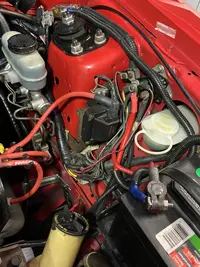
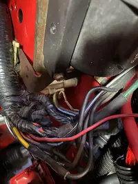
UPDATE #2 took the alternator off and had it bench tested, great shape! So back to trouble shooting - So on the drivers side fender under the coil cover here is what I found. A red power wire with an inline fuse connected to the lt grn/red wire on one end and the other end stuffed in one of the extra slots on the coil connector- pic included. I removed the wire connector and red wire and taped up the scar, you can see where the connector was located on the lt grn/red wire.
From the far side of where the connector was to the alternator, DMM tells me I have continuity so no line break? I have yet to get inside and trace wire into instrument panel but that seems like the next step. The wire as posted in here goes to the battery/AMP light which does not work so that may actually make sense since it is an integral part of the charging system. Question would be, what do I do if I have to replace the 500OHM resistor? I know replace it but where is it and where do I go to get the right one?
I do have a new positive and negative cable coming for the battery since the old negative cable and cable connector fell apart. Pic included. This is like a mystery!!
Alternator troubleshooting for 86-93 5.0 Mustangs:
Never, never disconnect an alternator from the battery with the engine running. The resulting voltage spike can damage the car's electronics including the alternator.
Revised 28-Nov-2018 to add warning that the instrument cluster must be in place and working for the alternator to charge
Red color text applies to cars with a 3G alternator.
Do all of these tests in sequence. Do not skip around. The results of each test depend on the results of the previous tests for correct interpretation.
Simple first step: Remove the alternator and take it to your local auto parts store. They can bench test it for free.
Use a safety pin to pierce and probe the insulated connectors from the rear when doing tests with the connector plugged into its' mating connector.
Engine off, ignition off, battery fully charged.
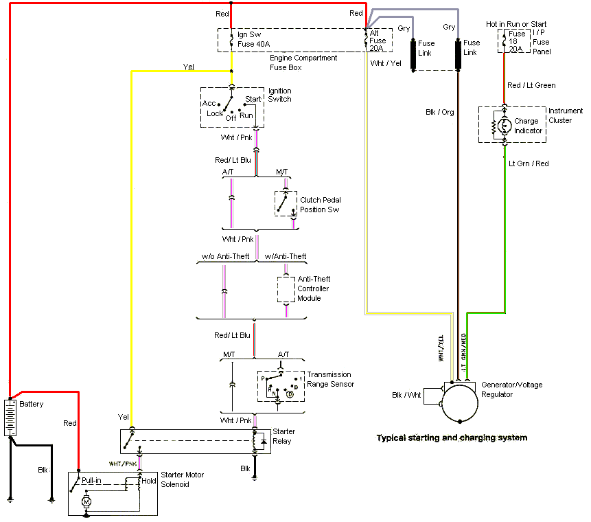
1.) Look for 12 volts at the alternator output. No 12 volts and the dark green fuse link between the orange/black wires and the battery side of the starter solenoid has open circuited.
3G alternator: Look for 12 volts at the stud on the back of the alternator where the 4 gauge power feed wire is bolted.
No voltage and the fuse for the 4 gauge power feed wire is open or there are some loose connections.
2.) Look for 12 volts on the yellow/white wire that is the power feed to the regulator. No 12 volts, and the fuse link for the yellow/white wire has open circuited.
The alternator MUST have the instrument cluster in place and working properly. The alternator warning light is a part of the charging circuit. No cluster, then no working alternator.
Engine off, ignition on, battery fully charged
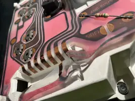
1.) The alternator warning light should glow. No glow, bulb has burned out or there is a break or bad connection in the wiring between the regulator plug and the instrument cluster. The warning light supplies an exciter voltage that tells the regulator to turn on. There is a 500 Ω resistor in parallel with the warning light so that if the bulb burns out, the regulator still gets the exciter voltage.
Disconnect the D connector with the 3 wires (yellow/white, white/black and green/red) from the voltage regulator.
Measure the voltage on the Lt green/red wire. It should be 12 volts. No 12 volts and the wire is broken, or the 500 ohm resistor and dash indicator lamp are bad. If the 12 volts is missing, replace the warning lamp. If after replacing the warning lamp, the test fails again, the wiring between the warning lamp and the alternator is faulty. The warning lamp circuit is part of the instrument panel and contains some connectors that may cause problems.
2.) Reconnect the D plug to the alternator
Probe the green/red wire from the rear of the connector and use the battery negative post as a ground. You should see 2.4-2.6 volts. No voltage and the previous tests passed, you have a failed voltage regulator. This is an actual measurement taken from a car with a working electrical system. If you see full or almost full12 volts, the regulator has failed.
Engine on, Ignition on, battery fully charged:
Probe the green/red wire from the rear of the connector and use the battery negative post as a ground. You should see battery voltage minus .25 to 1.0 volt. If the battery measured across the battery is 15.25 volts, you should see 14.50 volts
Familiarize yourself with the following application note from Fluke:
See http://assets.fluke.com/appnotes/automotive/beatbook.pdf for help for help troubleshooting voltage drops across connections and components. .
You will need to do some voltage drop testing of several of the wires.
Start looking for these things:
1.) Bad diode(s) in the alternator - one or more diodes have open circuited and are causing the voltage to drop off as load increases. Remove the alternator and bench test it to confirm or deny this as being the problem.
2.) The secondary power ground is between the back of the intake manifold and the driver's side firewall. It is often missing or loose. It supplies ground for the alternator, A/C compressor clutch and other electrical accessories such as the gauges. Do the voltage drop test as shown in the Fluke tech note link. Measure the voltage drop between the alternator frame and the battery negative post. Watch for an increase in drop as the load increases. Use the Fluke voltage drop figures as guidelines for your decisions.
3.) Bad regulator that does not increase field current as load increases. Remove the alternator and bench test it to confirm or deny this as being the problem.
4.) Bad sense wire - open circuit in sense wiring or high resistance. The yellow/white wire is the voltage sense and power for the field. There is a fuse link embedded in the wiring where it connects to the black/orange wiring that can open up and cause problems. Disconnect the battery negative cable from the battery: this will keep you from making sparks when you do the next step. Then disconnect the yellow/white wire at the alternator and the green fuse link at the starter solenoid/starter relay. Measure the resistance between the alternator end of the yellow/white wire and the green fuse link: you should see less than 1 ohm. Reconnect all the wires when you have completed this step.
5.) Bad power feed wiring from the alternator. Use caution in the next step, since you will need to do it with everything powered up and the engine running. You are going to do the Fluke voltage drop tests on the power feed wiring, fuse links and associated parts. Connect one DMM lead to the battery side of the starter solenoid/starter relay. Carefully probe the backside of the black/orange wire connector where it plugs into the alternator. With the engine off, you should see very little voltage. Start the engine and increase the load on the electrical system. Watch for an increase in drop as the load increases. Use the Fluke voltage drop figures as guidelines for your decisions.
Alternator wiring diagram for 87-93 Mustangs.
The following are diagrams courtesy of Tmoss & Stang&2birds
Alternator wiring diagram for 94-95 Mustangs.
Voltage drops should not exceed the following:
200 mV Wire or cable
300 mV Switch
100 mV Ground
0 mV to <50 mV Sensor Connections
0.0V bolt together connections
Alternator wiring circuit
Notice the green wire connects to a switched power source. The circuit contains a 500 ohm resistor in series between the switched power and the alternator. Connecting it to switched power keeps the regulator from drawing current when the engine is not running. The resistor limits the current flowing through the wire so that a fuse isn't needed if the wire shorts to ground.
Also notice the sense wire connects to the starter solenoid and it is fused. It connects to the starter solenoid so that it can "sense" the voltage drop across the output wiring from the alternator.
Fuse link for 86-93 Mustangs
Replacement parts:
14 gauge fuse link for stock alternator.
Bussman BP/FL14 Fusible link
AutoZone
Dorman - Conduct-Tite 14 Gauge Fusible Link Wire Part No. 85620
Advance auto parts #85620
Pep Boys - SKU #8637594
See the following website for some help from Tmoss (diagram designer) & Stang&2Birds (website host) for help on 88-95 wiring;
http://www.veryuseful.com/mustang/tech/engine/ Everyone should bookmark this site.
94-95 Mustang wiring diagrams
http://www.veryuseful.com/mustang/tech/engine/#95-95Diagrams
Complete computer, actuator & sensor wiring diagram for 91-93 Mass Air Mustangs
http://www.veryuseful.com/mustang/tech/engine/images/91-93_5.0_EEC_Wiring_Diagram.gif
Complete computer, actuator & sensor wiring diagram for 88-91 Mass Air Mustangs
http://www.veryuseful.com/mustang/tech/engine/images/88-91_5.0_EEC_Wiring_Diagram.gif
Ignition switch wiring
http://www.veryuseful.com/mustang/tech/engine/images/IgnitionSwitchWiring.gif
Fuel, alternator, A/C and ignition wiring
http://www.veryuseful.com/mustang/tech/engine/images/fuel-alt-links-ign-ac.gif
O2 sensor wiring harness
http://www.veryuseful.com/mustang/tech/engine/images/mustangO2Harness.gif
Vacuum diagram 89-93 Mustangs
http://www.veryuseful.com/mustang/tech/engine/images/mustangFoxFordVacuumDiagram.jpg
HVAC vacuum diagram
http://www.veryuseful.com/mustang/tech/engine/images/Mustang_AC_heat_vacuum_controls.gif
TFI module differences & pin out
http://www.veryuseful.com/mustang/tech/engine/images/TFI_5.0_comparison.gif
Fuse box layout
http://www.veryuseful.com/mustang/tech/engine/images/MustangFuseBox.gif
Mustang 5.0 Lights and Radio schematic, by TMoss:
http://www.veryuseful.com/mustang/tech/engine/images/mustangFoxLights-Radio_diag.gif
87-92 power window wiring
http://www.veryuseful.com/mustang/tech/engine/images/mustang87-92 PowerWindowWiring.gif
93 power window wiring
http://www.veryuseful.com/mustang/tech/engine/images/mustang93PowerWindows.gif
T5 Cutaway showing T5 internal parts
http://www.veryuseful.com/mustang/tech/engine/images/5_Speed_Cutaway_Illustrated.jpg
Visual comparison of the Ford Fuel Injectors, picture by TMoss:
http://www.veryuseful.com/mustang/tech/engine/images/Ford_Injector_Guide.jpg
Convertible top motor wiring
http://www.veryuseful.com/mustang/tech/engine/images/mustang88VertTopMotorCkt.gif
Engine mounted fuel injector harness
http://www.veryuseful.com/mustang/tech/engine/images/mustangEngineHarness.gif
Location of the TPS, IAB, and the 10-pin connectors on a 5.0, picture by TMoss:
http://www.veryuseful.com/mustang/tech/engine/images/TPS_IAB_Pic.jpg
Starter circuit
https://www.stangnet.com/mustang-forums/attachments\21328
Alternator diagram for 94-95 Mustangs.
http://www.veryuseful.com/mustang/tech/engine/images/Mustang-94-95-Alt.gif