Fox Please help: Electrical load creates missfire ?!

Multimeter won't show electrical noise, you need an oscilloscope.
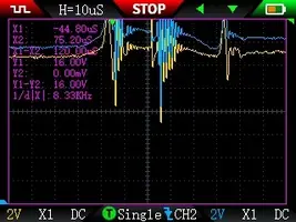
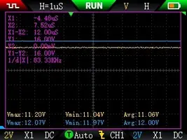
Update: I've used an oscilloscope to capture TFI module and would like help get the right diag about finding.

Here the wiring for TFI:

6-PIP
5-Spout
4-Start Signal
3-Run Power
2-Coil
1-Ignition ground

I've used: Yellow channel VS Blue channel.

All traces were captures while idling except: "Start Signal vs RunPower_IgnitionOn_02.bmp" witch is with only KOEO.

Let me know,

Thanks
 

Attachments

  • PIP vs Run Power_02.webp
    PIP vs Run Power_02.webp
    17.4 KB · Views: 63
  • PIP vs Start Signal_01_v2.webp
    PIP vs Start Signal_01_v2.webp
    17.6 KB · Views: 64
  • PIP vs Start Signal_02_v2.webp
    PIP vs Start Signal_02_v2.webp
    16.9 KB · Views: 69
  • Start Signal vs RunPower_01.webp
    Start Signal vs RunPower_01.webp
    17.9 KB · Views: 69
  • Start Signal vs RunPower_01_v2.webp
    Start Signal vs RunPower_01_v2.webp
    17.6 KB · Views: 66
  • Start Signal vs RunPower_IgnitionOn_02.webp
    Start Signal vs RunPower_IgnitionOn_02.webp
    17.1 KB · Views: 63
We're just going all the way down the rabbit hole.


I'm not certain what there is to let you know.

Let [us] know if scoping the TFI module helps you in any way, shape, or form. If you suspect the module is bad, swap it.

TFI module has been replaced by a motorcraft and issue still there.

What I'm curious or what I should say, I'm wondering if its "normal" to get spike from 7,5v to 16v+ on "start signal" and "run power" from TFI while idling.

I've probed there because that was the easiest place, not because I suspected TFI. I'm new to scope so that why I'm asking help.

Thanks
 
Think he was asking about the wires, not plugs.
yes, the plug WIRES, similar issue but a little different, solid core wires were install on a friend's car, brand X with an HEI distributor, the solid core, well non-resistor wires anyway, high RPM miss, you usually get that annoying radio buzz, not fun like a beer buzz.
he didn't have a radio :doh:
 
Did we verify that the shielding on the wiring to the ECU was intact? Also, if you’re getting 16v anywhere, just wondering if a bad regulator on the Alt could be creating unusual symptoms?
I'm new to oscilloscope since that issue so it's a give or take.

Measurement has been taken on the TFI, both voltage (start signal and run power).

I have changed the alternator and issue is still the same. I do have a third one brand new on the shelf.

It doesnt make sense to me 2 on 3 are defect but I will do the swap and report back because this make me sick not finding the cause....

Thank you guys :-)
 
PIP and SPOUT should have a square wave.
Pin 3 should be battery voltage with key on and cranking. Coil trigger is a ground to the primary side of the coil. The module turns off the ground to fire the coil.
I can't make anything from those pictures.
What's what? Where are you testing from.
 
PIP and SPOUT should have a square wave.
Pin 3 should be battery voltage with key on and cranking. Coil trigger is a ground to the primary side of the coil. The module turns off the ground to fire the coil.
I can't make anything from those pictures.
What's what? Where are you testing from.

Hey @CassieL, thanks for taking time reading my thread and trying to helping me.

First, I'm trying to use oscilloscope (first time user) to see if that will help me out finding the root source of the issue and fix it after all.

I know PIP and Spout are square wave but curious about result of what I've scoped.

Let me recap issue fast and easily. When my engine is running at 2K or higher, a high load spike like electrical fan, heater blower, will create a misfire and as megasquirt user, in logs, we see RPM jump to the moon (30K RPM !) When alternator is unplugged, I cant reproduce the issue. A lots of thing as been verified and replaced like distributor, TFI module, Alternator, plugs, wires, etc and now, I'm trying to see with oscilloscope.

I've hookup scope by backprobing TFI module while engine idling.

If you look at "PIP vs Run Power_02", PIP is yellow while Run Power is blue line. It is normal to get noise like this? Same question for "PIP vs Start Signal_01_v2", PIP is yellow while Run Power is blue line?

If you look at "Start Signal vs Run Power_01" Start Signal is yellow while Run Power is blue line, I've done that test cause in diagram, the 12V is not coming from the same source so I tought it could be interesting to capture both.

Thanks
 
Last edited: