Status
Not open for further replies.
I found an engine cut-away:


59036b681d5b9e07947b23ce.jpg

Is that the 250hp Singer head or the 300hp? Or do they rate those in SPH? (Stitches per hour)
 
  • Like
Reactions: 1 users
  • Sponsors (?)


Is that the 250hp Singer head or the 300hp? Or do they rate those in SPH? (Stitches per hour)

The only way to tell from the outside is to look and see if the water pump is reverse rotation. :shrug:

To put the car in reverse, you just turn that little knob backwards until you're back far enough.
 
  • Like
Reactions: 1 users
The only way to tell from the outside is to look and see if the water pump is reverse rotation. :shrug:

To put the car in reverse, you just turn that little knob backwards until you're back far enough.


Wait....is that the rare, export only, tall deck siamesed block? I thought Singer destroyed those and all the tooling in 89.
 
  • Like
Reactions: 1 user
So if your smart, you can reverse engineer the horspower tune to make 400 flywheel net horsepower and 267rwhp at the bags.


You pop it in the engine anaylser, and find the cam, head and intake and exhaust to make power of 400 hp at 6500 rpm. You would need an aspirations index of 4111 to do it.

That's how the old timers did the target engine tuning.

So just so I understand this and the previous in the previous post. Your saying that a split runner manifold is more efficient then a plenum manifold? And used more in Australia. I always thought the plenum during reversion, (in part and mid throttle and even wide open throttle) helps fill the other cylinder from the shock wave from the closing valve. With single runners this throws this efficiency out the window. I really question this as we all know on the exhaust side it is proven that a tied exhaust makes more power by scavenging other cylinders vs zoomier type header. To my knowledge the intake behaves very simular to the exhaust as far as moving air.
 
  • Like
Reactions: 1 user
Its all good. Its just split in a different way.


Here is the Aussie Ford EF/EL/AU/BA/BF/FG Broad Band Modulated intake manifold

BA%20intake%20manifold.jpg


The measure of real performance is how broad the torque is and how many horsepower the engine makes at the lowest possible power peak.

Famed AVECO 305 cubic inch, 5 liter Touring Car racer Larry Perkins said

460 hp at 6700 rpm beats 462 hp at 6900 rpm.

305*6700/460=4442
305*6900/462=4555

Two extra horspower is not worth it if the engine has to carry 200 extra rpm.
But 14 extra horsepower is okay if the engine has to carry 200 extra rpm.

305*6900/474=4440

That's the way the old timers did it. These days, engine builders look just to maximum power peaks


You can make in the torque lower rev range (the measure is lb-ft per cubic inch), and maintain power high up (the measue is the Aspirations Index), but if you do everything well with the tune, you can have a meaty torque band and a nice power peak.


The R-I-G-H-T intake volume increases mid range torque, The R-I-G-H-T intake volume helps peak power. The right volume depends on what RPM the engine is doing. It depends on the engine. On my wifes ACIS equiped engine, the throttle blades are effectively lengthened when the throttle is below 4500, making the the intake manifold run longer, and about 2 liters in capacity. Past 4500 rpm, it shortens to about 50%, or 1 liter.

On a 4.1 liter engine, the EFi runner has 2.3 liters of capacity without the extra butterflies. 50%

On a 4.0 SOHC or DOHC, the dual intake Ford manifold, it has extra volume to call on at part throttle to improve torque, then it drops off at wide open throttle to ensure power increases.

The runners are each independent.


The basic thing is that a working range of an engine always creates fuel standoff....the haze of air fuel back from the point of induction, backing off to and frow like an alternation current, always moving forwards, but at various times, pushed back like a boats bow wave. The intake runner has to just hold fuel standoff at various points, to give the engine a chance to consume the atomised air fuel mix.

By altering the volume of the intake runners at various revs, you can optimise the torque and peak power curves to the fullest.

Toyota, Ford, Honda typically do this by adding a multiple valve independent runner system.

Mike can take or leave somting like this b@$=@rd of a thing... my wifes Acoustic Control Induction System.

RAV4_3s_ge_engine_with_ACIS_2.jpg


I hate it, but it works.

ACIS_AcousticControlInductionSystem10F2.jpg
ACIS_AcousticControlInductionSystem20F2.jpg


acis.jpg


acis_001.jpg


RAV4_3s_ge_engine_with_ACIS_3.jpg


Celica_3s_ge_engine_with_ACIS.jpg


Caldinast25_3s_ge_engine_with_ACIS_4.jpg


RAV4_3s_ge_engine_with_ACIS_1.jpg
 
Last edited:
  • Like
Reactions: 3 users
The 3SGE engine is a nightmare, but its intsake runners are drapped right down the side of the engine, with the injectors embeded into the intake manifold. Its the nastiest piece of crud to work on, bar no other car. But if you stole one off an MR2, the second generation 2 liter, you'd see how easy it is to do the same thing on a Cross flow.


Thinking out load here, Mike might be better just running tubes to the ports, and remote mount the BMW E46 M3 intake as a Band expander to drive the total volume and intake runner length up below 3800 rpm. Target volume might be, say, 60-70% of the engine volume. Past that, the throttles can close, and the runner volume can be cut in half to a target 30%.

My wifes RAV4 G type engine does the same thing, voume closed below 4500 rpm is 2 liters, about 4500 rpm, 1 liter.


View: https://www.youtube.com/watch?v=6BwyXKLJ4Qg


View: https://www.youtube.com/watch?v=9fYDd94pf98


b57dadas-960.jpg


The narrower centre spacing of the BMW M3 6 Intake Throttle bodies at 3.6" could be accomodated easily, and the lower intake would be spaced with each runner 4.08" appart, same as the bore spacing.


Just copy my RAV4 intake, but make it a 6 cylinder one, using the M46 throttles, unchanged.

That way, you could target your ideal horsepower and rev range, just like the Ram Chargers did on the old 413's and 426's. Only, you could also optimise it for maximum torque in the middle range.

All pictorial material below is the work and property of Malcolm Graham

3sgeplenum1.jpg


3sgeplenum4.jpg


gen2geintake.jpg
 
Last edited:
Or Dirty Deans Dyslexic Delusions of Horsepower...

What little I think I've learned, I thought I'd share.

How this helps Mike build a better Mouse Trap, who can say?

The pictures are here to help Mike sort out what he wants to do.

I didn't mean to go so far, honest.....I'll receed back into the scenery for a long while so everyone gets a fair airing.

One thing in closing.


All the "turbo" X flows and DOHC Aussie Falcons later ditched the dual runner intake because a turbo is basically an expanding iron lung, and it was hard to tune under on and off boost conditions.

The stock 362 to 423 hp system became like this


20121023_154528.jpg


The X flow and SOHC intake, it mounted like this. The later SOHC is a 250 crank and conrods, with a different block and undersized pistions, but it still has a driven shaft for the distributor, so all that 1988-1993 OHC stuff was pretty much interchangable.

It had TFi from 1985 till 1993, so dats a distributor you see, and a water pump could go in that spot instead. Maybee.

utelatest-115_zpsa43c7aa5.jpg


Latestutepics-22_zps04628bfc.jpg


Utelatests-1_zps5078cd62.jpg


Latestutepics-23_zps4c5c3dca.jpg


Back to the Normally Aspirated "Monzta", people. Its gonna be epic.
 
Last edited:
  • Like
Reactions: 1 users
Im late to the party here, and realize this opinion is better off whispered into the wind, but I REALLY think you should hang on to all of the turbo stuff until you get the NA engine running and driving. That way, when you realize it sucks, you can fall back to that post a while back when you said, "THAT WAS FREAKING AMAZING!"
 
  • Like
Reactions: 4 users
Ok then, so the take-away from the last couple of pages is:

Don't let me go away from this thread too long, or it gets filled up with pictures and links to engines and cars, (related to the current project,.... or not) and sewing machines dating back to somewhere in the paleolithic era.

And after taking all of the input/contributions/comments into account,
This is what I've decided to do:
The Sewing machine thing is definitely out. Just like the machine gun thing, The 80's K.I.T.T. wanna be dash, and a whole bunch of other "What tha's" that our head care taker offers up as advice in this build. I'm really starting to wonder about the assortment of "Don't push" buttons Noobz puts in the flight simulators that he has a hand in building.:O_o:
I'm gonna put a common plenum "sandwich" in between the TB's and the Head. There are several concepts I'm working on...
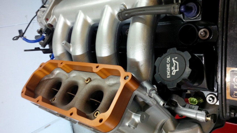
#1. "The box".
Just like it sounds,...it'll be a box, (or it could be a tube) probably angled up to provide a common plenum. One plate side mounted to the head configured at the 4.08 port spacing, the other plate side configured for the E46 TB's. Little notches cut in at the top of the box to allow the injectors to clear. I'd radius the opening on the head side to look like Dean's MR2 box.
b57dadas-960.jpg

Eliminate everything else in the pic....Just the part with the copper spacer would make up "The box".
#2. "Holy Tubes in the box Batman!"
Way more involved. The box seals the individual tubes on both mating surfaces. The tubes keep the individual relationship of each TB mated to each port intact, except somewhere (top, side(s), bottom, all around),.. each tube has a hole(s) in it to allow for the commonality of the open plenum.
#3. "Linked tubes". AKA the "outtie box"
No box,....individual transition tubes to allow for the bore spacing differential,..but has similar sized tubing linking each tube together..Vacuum taps plumbed between each port tied together with hard lines like a nitrous fogger system providing one common vacuum port for the MAP sensor to read off of. Does what #2 does externally as one sealed piece.

By far, #1 is the easiest to duplicate,....I could make something like this in a day. I'm wondering how impacted the benefit of having the individual TB's would be if I sandwich a box in between for the sake of the MAF.
#3 would be the second easiest to build, but will it work? It'll still have the same common plenum that the box has,(albeit smaller) but keeps the relationship of the individual TB/port intact. I also think as a finished product,it would look better than a box....(Not to mention the cool factor that fogger looking hard line vacuum tap would add). The curiosity pops up as to whether or not it solves the reversion/common plenum purpose adequately?

I looked at my head....Excepting the 1" port matching, It is completely unmolested. Although I did some bowl work and smoothed the transitions of the port to the valve seat originally,...I took this head after that to the machine shop where they assembled everything. Looking into the respective ports does not come close to looking like anything was ever done.

I need to deal with blending the guide bosses, and pay more attention to the transitions to the valve seat area. (w/o phcking up my existing valve job) The exhaust port has a rather large bump on top of the port roof...wondering what happens when you put an aluminum burr to that? (Pay attention here Dean)

The objective here is to not ruin an irreplaceable head...From what I'm reading from you, I'm gonna be able to get what I'm looking for (250whp/300rwtq) just by judicious and careful guide boss/bowl blending work. I'd just as soon not attempt raising the intake port roof, but I wonder how in the hell a 1.7' valve gets it's air through a 1.39" cross sectional port?:shrug:

Raising the roof also affects the shape of that port at the entry point, which directly impacts my choice for how to mate the TB's to it. An oval, or egg shape isn't as easy to accomodate when trying to get a curved piece of 16 ga tubing to fit that form. But......
I'll do what I need to do.
 
  • Like
Reactions: 2 users
Latestutepics-22_zps04628bfc.jpg


I LOVE how this intake looks like a header. It would be awesome to essentially have symmetry on either side, but obviously your stand alone TBs keep that from working.

At any rate, looking forward to see what you come up with Mikey.
 
  • Like
Reactions: 1 user
Mike I think individual runners for each TB would perform the best and give some runner length, no common plenum. You can then tap each runner as stated above and hard line them to a vacuum resorvoir, this will act as a damper for the the map signal so to smooth the pulses.

A common plenum will give you 0 zilch nada for runner length and hugely effect the low speed torque output methinks
 
Im late to the party here, and realize this opinion is better off whispered into the wind, but I REALLY think you should hang on to all of the turbo stuff until you get the NA engine running and driving. That way, when you realize it sucks, you can fall back to that post a while back when you said, "THAT WAS FREAKING AMAZING!"

That's not the problem.....Let's put it into some future context to fully appreciate my concerns:

* taken from a couple of pages from your thread...

https://www.stangnet.com/mustang-fo...-stuff-seriously.879126/page-168#post-9022985

But then we have...

https://www.stangnet.com/mustang-fo...-stuff-seriously.879126/page-169#post-9023061

Once exponential horsepower enters the picture, the slightest error or miscalculation leads to catastrophic failure as you are well familiar with.

In my case,.... I was always playing Devils advocate....

The power felt great,....but how bad would it suck if/when there's that sudden loss of power,...drop in oil pressure, or big fcking bang immediately afterwards?

I'd rather drive it at half the power for a long time, than twice the power for a minute.
 
  • Like
Reactions: 1 user
Mike, I definitely understand the point you're trying to make, but you were also trending towards turning it up and up and... Why not just keep it at a lower, reasonable PSI and let it alone? I'm just worried you're going to put yourself through all the work to make it NA and then despise it. Then you'd have to re purchase everything and do it all over.

If I'm wrong after you drive it NA, so be it. Then sell the parts.
 
  • Like
Reactions: 3 users
Status
Not open for further replies.