Build Thread Mustang5L5's Build Thread -

Status
Not open for further replies.
Here’s how it was originally configured. The screens were open to the elements. The walls rotted out.
F88C4189-6272-48E4-8460-273632651379.jpeg
E7FEA57C-CC9C-4E5E-A395-F89FD9465F3D.jpeg

D472B79D-E44A-4698-973C-FAF543D95717.jpeg

so I blew open all three walls and rebuilt them.
7DC48B62-CB27-411C-A9BB-7D173D326E09.jpeg

E81BBA6D-6858-466E-9505-E0CFFD00AD37.jpeg
 
  • Like
  • Hell Yeah!
  • Wow
Reactions: 2 users
  • Sponsors (?)


I have the tracking number for the replacement. Should be here mon. Was really pleasant to deal with Baer on this. No sweat.

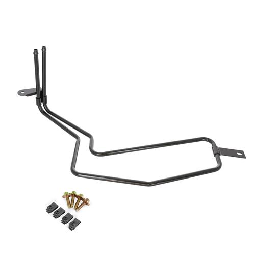
Got my 94-98 cooler. Unfortunately it mounts the same but it’s shorter by a tad. The good thing this version was dirt cheap, so I will use the earlier model and eBay the more desirable 03/04 cobra version.

I’m going to have to modify it slightly to clear the condenser
2509ABBC-A23D-40F5-9EF9-2D9095ED20A3.jpeg
Did I miss how you plumb one of these in? Are they barbed for the return line side hose that clamps on? Thanks.
 
Did I miss how you plumb one of these in? Are they barbed for the return line side hose that clamps on? Thanks.
Yes. The are barbed just like the factory PS cooler for the fox. The pass through the rad support like the fox and the bracket near the 90* bend lines up with the original mount mount.

it’s the body which hits the condenser and the far mount doesn’t line up with anything.

my thinking is if I can carefully bend it 90* and up slightly, I can make a bracket for the far end.

i will try to tackle this after the bumpsteer stuff is done. They are both still on my bench.

I think the part number for the shorter one is F6ZZ-3D746-AA and the long one is 2R3Z-3D746-AA and they are still available new.
 
Last edited:
Did I miss how you plumb one of these in? Are they barbed for the return line side hose that clamps on? Thanks.

ok, I was curious an had an hour so I started trying to put it in.

between the two, I decided to use the shorter one. I could have used the longer one, but I paid more for it, and figured the short one would be plenty for my needs. I paid $20 for the short one. The long one would fit without the hood support bar. So back on eBay it goes.

first step was pulling off the support bar. Prt the two tabs up and off it comes
5D546ADF-AC53-49BB-BD61-F26EB725610A.jpeg
518BE635-C411-4B14-B268-02B2F0509E84.jpeg


after tgat, the tubing bends very easily, so care must be taken. I turned the tubes 90 degrees and added a kick up abd out. End result compared to the untouched 04 cobra cooler
D45914EE-E5F5-4F0E-9389-2C7497DAD05C.jpeg


Stuck the bracket back on and test fit. I’m 90% of the way there, but looks like this will work. Just needs a few small tweaks.
F3BBA566-BD67-4739-A9DA-9B578B9857DC.jpeg
CEAD2E34-AF8A-44A0-B8B2-44C91B6B2294.jpeg
CB14C313-D25A-4E1E-8215-3B490941FE95.jpeg


here’s the other mount. I’ll trim the old bracket off and drill a hole and mount it to the same hole that the hood support bracket mounts to. If I ran the 04 cobra cooler, the hood support bracket would need to go. With the shorter cooler, the loop tucks right behind it.
A4C1283A-1061-4E59-BB44-6CEF1B692A1A.jpeg


Obviously it will need a (light) coat of paint as well when I’m done
 
Last edited:
  • Like
  • Useful
Reactions: 5 users
So went into the garage to start measuring bump steer. It did not go well. On the lowest stack, the bumpsteer was terrible. Didn’t even need to measure it, you could visually see the measuring board toeing out under bounce.

that means the tie rod needs to go up. Except, I was already up. I had the tie rod all the way up to the silver spacer. It needed to go further
3809ED29-04C2-4809-B0F1-20FDF911B476.jpeg


so for the hell of it I I pull the main silver spacer and measure a small gold spacer against the spindle. Not the proper way this kit installs, and not safe to run, but I wanted to see if it got better. It did.
C89702CD-2C66-4B97-B6D4-5F77B14E51E5.jpeg


I called it a night, but I have a parts mismatch somewhere. Either I move the rack down, or swap back to the 94-95 spindkes (and ream them for the bolt-thru kit), or get another set of 96+ spindkes and run the tapered stud bumpsteer kit which allows the tie rod to sit closer.

I want to measure a few more times with the tie rod right up against the spindle to see if it starts to go the other direction. Then I’ll talk to MM.
 
I thought the 1.44" long spacer was used only if running 94-95 or the stock 4 lug spindles,if you have 96+ you would use the 2 shorter 5/8" bolts that are supplied in the kit and no long spacer....or maybe not???

Edit: Do you know why are there 2 different lengths of bolts supplied in the kit?
 
I thought the 1.44" long spacer was used only if running 94-95 or the stock 4 lug spindles,if you have 96+ you would use the 2 shorter 5/8" bolts that are supplied in the kit and no long spacer....or maybe not???

Edit: Do you know why are there 2 different lengths of bolts supplied in the kit?

I am using the shorter bolt, but looking through the instructions I don’t see any mention of not running the big 1.44” spacer. In thread searching I see mention of machining it down however

I think the long bolt is for folks running 94-95 spindles. The mount point is 1.02” higher. You can see in my pic that I don’t really have an extra 1.02” of thread so with those spindkes some folks need the wider range.

actually, I think the solution here is to lower my steering rack down. I’m at the highest of 5 positions. If I lower the rack, it may get me in range. I also think moving to the upper control arm bolt holes would do it too, but I’m not lowering my car far enough to use those.

I’m going to measure where it would need to be in this configuration. If it’s close enough to the spindle, I might swap back to my 94-95 spindkes to pull the wheels back in the 5mm. I might need it with my new wheels (which one is on the way for test fitting :) )

I’ll email Jack Hidley in the AM.
 
I'm wondering about the bolts,so if using the earlier spindles they want you to make up your own additional 1" spacers to install along with the 1.44".
You would almost need to do this in order to run the longer bolts.
Looking forward to a solution to your issue,I may be in the same boat soon.
 
I don’t have to tell you that a 94/95 spindle has a raised dog leg that’s gonna fix your problem. If it worked with regard to fixing your bump steer, the current “closer“ adjustment with the spacer under the tie rod mount is still gonna be fine I’d imagine..as it still allows the rod end to pivot or swivel.. But you still have a ways to go i’d think..
Since it’s all bolted together, i’d get rid of the spacer all together and put the rod end right against the mount point to see if it gets close to where it needs to be.
 
I'm wondering about the bolts,so if using the earlier spindles they want you to make up your own additional 1" spacers to install along with the 1.44".
You would almost need to do this in order to run the longer bolts.
Looking forward to a solution to your issue,I may be in the same boat soon.

Correct. That's why they recommend the 96+ spindles. It shortens the spacer stack by 1".

1607443077268.png


Basically you are trying to avoid this

1607443828423.png


BTW, the above kit is installed incorrectly. The large spacer should be up against the spindle with the small spacers between it and the tie rod end.


However, in my case it appears I may need to raise the pivot point slightly to run this bolt thru kit. That means going back to 94-95 spindles. I'm not opposed to that, but I will need to take both sides apart, ream the tie rod holes out, and then clean up and paint and reassemble and then remeasure. I'm just curious why guys are running setups like above with 94-95 spindles, and i look like i will be pretty close.
 
Last edited:
I don’t have to tell you that a 94/95 spindle has a raised dog leg that’s gonna fix your problem. If it worked with regard to fixing your bump steer, the current “closer“ adjustment with the spacer under the tie rod mount is still gonna be fine I’d imagine..as it still allows the rod end to pivot or swivel.. But you still have a ways to go i’d think..
Since it’s all bolted together, i’d get rid of the spacer all together and put the rod end right against the mount point to see if it gets close to where it needs to be.

I agree.

I think i have a few solutions here. I'm just trying to think through as to which is the most ideal solution. Lower the steering rack, or change the spindle. The easiest solution might be to lower the steering rack. The best solution (IMHO) is to swap back to the 94-95 spindle, even though it will be the most amount of work. This means going back to the machine shop to ream them for the bolt through bump-steer kit. (unless i'm in range to run the tapered-stud bumpsteer kit I have. The pros here however is pulling the wheel back in that 5mm. Yeah, it's only 5mm, but I might need to run a 5mm spacer on my new wheels to clear the Brembos. I don't want to start pushing this wheel out too far

I agree with your final statement. Since I have it together, i should move the tie rod end right up to the spindle mount and see where it gets me. If it continues to toe out, then i need to go higher. At least i can get an idea of where the tie rod end needs to be, and then make a decision there.

The big silver spacer needs to be present for stability. I can't put the tie rod permanently up against the spindle mount according to MM. I can, however, machine it shorter, but I think I'm going to end up being right up against the spindle or slightly into it. That forces me to either change the spindles, or lower the rack. I think i'd rather gain that 5mm back

I do want to ask MM and get their opinion. I haven't done so yet due to a very busy work day so far.
 
Last edited:
I would be suspect of the length between the tie rod end and the spindle mount(in the pic above), that's a long way and bolt integrity would be my concern. Lump, bumps and aggressive cornering would worry me but what do I know.
 
I spoke to MM. SInce my tie rod wants to be closer to the spindle, I can safely remove the large silver spacer.

So now that I know I can ditch it, I will continue to measure and see what my spacer stack should be.
 
A lot of this is flying over my head since I've never really read up on it. Forgive me if this is a nonsensical question, but are the offset rack bushings still necessary with the kind of setup you're going with? It looks to my untrained eye like standard bushings—or at least having them in the standard position—would help get you where you need to be?
 
A lot of this is flying over my head since I've never really read up on it. Forgive me if this is a nonsensical question, but are the offset rack bushings still necessary with the kind of setup you're going with? It looks to my untrained eye like standard bushings—or at least having them in the standard position—would help get you where you need to be?

Yes, they are still necessary.

The reason is because the MM K-member raises the mounting points for the LCA's. The bottom holes are 1" higher than the OEM mounting location (relative to the rest of the car) and the upper holes are 2" higher. The steering rack has offset holes to raise (or lower) it 1/4" or 3/8". So you raise the LCA mount points 1", but the rack can only go 3/8" That's why there's a bumpsteer kit with a stack of washers to make up the difference.

The offset rack bushings here don't really apply in cases where a stock K-member is being used. This is more or less the entire MM system being setup to work with each other. That's why I have 96 spindles otherwise i'd have a HUGE bumpsteer stack like what I posted a few posts up.
 
Last edited:
You are right though that lowering the rack down to the center position (or lower) would get me to where ineed to be, but the best solution is a setup where the spacers between the tie rod and spindle as as minimal as they can be to reduce flex, and shudder from the steering as the wheels turn. So you want the rack up as high as you can go.

I'm almost where I need to be with the stack setup like the 2nd photo.
 
Ok, crisis averted. After learning the silver spacer doesnt necessarily need to be first, I adjusted my stack.

this is damn near dead on. MM calls for no more than 0.020” per inch of travel. I have 0.040” total for 3” bounce and 3” droop. That’s about as close as you can get to eliminating bump steer.

here’s where I am with about 0.324” of a stack.

172EBB8C-AEAC-46D0-BA56-1B2793B105B1.jpeg


I know they say “just make the arms Parallel”, but I’d like to point out that adding a 0.010” shim here makes a huge difference in the bumpsteer curve. So eyeballing it won’t necessarily mean perfect, but it gets you close.

now to actually sit down and plot my curves to figure out what my actual stack should be. Then I get to do the other side. I found the “ballpark” by zeroing my Guage and watchinh how far the needle swept. Now I have to spend the time to dial it in. The target is to have as little movement at ride height and then with 1-2” of bounce (upwards movement) so that as your driving down the road hitting little bumps the car doesn’t want to dart.

Now, If you had 94-95 spindkes in this MM setup, add another 1.02” of stack in there. That’s why the 96+ spindkes are recommended, but not totally required.
 
Last edited:
  • Like
Reactions: 1 user
Status
Not open for further replies.